Carrier® Dedicated Outdoor Air Unit 62X: Quarterly Maintenance
This quarterly maintenance helps you check the settings (controls, operating temperatures, operating pressures, power and control voltages) and operation.
Carrier® Dedicated Outdoor Air Unit 62X: Quarterly Maintenance
This quarterly maintenance helps you check the settings (controls, operating temperatures, operating pressures, power and control voltages) and operation.
MAINTENANCE
Prior to any maintenance or service to the unit, shut off, lockout, and tagout the electrical disconnect and fuel valve (if applicable) that supplies the unit in accordance with OSHA regulations and, if the unit includes electric or gas heat, allow ample time for the unit to cool. After maintenance is performed or the unit is serviced, the unit shall be re-commissioned per the start-up procedure.
Installation Code and Quarterly Inspections
All installation and service of Carrier’s 62X equipment must be performed by a contractor qualified in the installation and service of equipment sold and supplied by Carrier, as well as conform to all requirements set forth in the manuals and all applicable governmental authorities pertaining to the installation, service, operation, and labeling of the equipment.
To help facilitate optimum performance and safety, Carrier recommends that a qualified contractor conducts, at a minimum, quarterly inspections of your 62X Series equipment and perform service where necessary, using only replacements parts sold and supplied by Carrier.
QUARTERLY
Follow the entire start-up procedure at this time and check settings (controls, operating temperatures, operating pressures, power, and control voltages) and operation.
Unit Exterior
CABINET EXTERIOR
UNIT LOCATION
Direct Drive Supply and Exhaust Fans
BLOWER WHEEL
MOTORS
Inspection
Lubrication
Lubricating Instructions
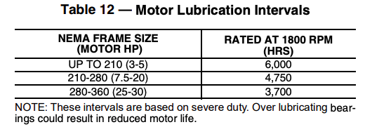
Before greasing, be sure fittings are clean and free from dirt. Remove grease relief plug or plate and, using a low-pressure grease gun, pump in the required grease. Do not over-grease. Re-lubrication intervals are specified in Table 12. After re-lubricating, allow motor to run for 10 minutes before replacing relief hardware.
IMPORTANT: In general, it is not recommended to mix greases of different brands. The mixing of different types of thickeners may destroy the composition and physical properties of the grease. In the event that a different grease is required by the end user, the following steps can be taken. Using the Lubricating Instructions, open grease outlet and purge the system as much as possible of the old or unwanted grease. Repeat this same operation after one week of service.
Condensing Fans
Refrigeration Circuit Components
EVAPORATOR COIL
CONDENSER COIL
COMPRESSORS
Condensate Drain Pan and Drain
Dampers
DAMPER MOTOR/LINKAGES
Energy Conservation Wheel
BEARINGS
DRIVE MOTOR
DRIVE BELTS
SEALS
WHEEL
The wheel is somewhat self-cleaning through its normal action of rotating in and out of counter current airflow streams.
In the event that routine quarterly inspection indicates that there is dirt or dust buildup within the wheel causing an excessive pressure drop, then wheel cleaning should be performed as follows:
Gas Heater
GAS LINE
Check for gas leaks
MANUAL SAFETY SHUT OFF VALVE
Check for gas leaks.
DIRECT SPARK IGNITER
Check for cracked ceramics, excessive carbon residue, or erosion of the electrode. Replace as required.
GAS VALVE
Check that gas valve seat is not leaking.
BURNERS
Soft brush or vacuum inside burner, at burner ports, and at air inlet between burner and manifold pipe to eliminate accumulation of lint and/or dirt.
HEAT EXCHANGER
Inspect for cracks, sagging, bending, or distortion. Clean with vacuum and/or stiff brush.
DRAFT INDUCER
Clean with compressed air or vacuum.
VENT PIPE/TERMINAL
Venting must be intact. Using a flashlight, look for obstructions, cracks on the pipe, gaps in the sealed areas, or corrosion. Clean vent terminal.
CONDENSATION DRAIN
Check for blockages.
Electric Heater Wiring and Wiring Connections
Check all wiring connections. Tighten as necessary. Check internal wiring. Replace as necessary with type THHN 221°F (105°C), 600V, 16-gauge wire or equivalent.
CONTROL PANEL
Check heater control panel for dust/dirt and moisture. Clean as necessary.
HEATING ELEMENTS
Check heating elements for dust/dirt buildup and/or broken elements. Replace elements and/or clean elements with low pressure air as necessary. Check element male/female chassis insulators for breaks and/or cracks. Replace as necessary. Check element support frame insulators. Replace missing or broken insulators as necessary
Filters
Filters should be checked for dirt restriction on a monthly basis (or as required). Replace filters with filters of equal specification when they appear dirty.
Source: Carrier (www.shareddocs.com)

