AERO® Semi-Custom Central Station Air 39M: Maintenance
The procedures here focus on the general maintenance of your equipment, inspection and fan shaft bearing removal.
AERO® Semi-Custom Central Station Air 39M: Maintenance
The procedures here focus on the general maintenance of your equipment, inspection and fan shaft bearing removal.
! CAUTION
Electric shock hazard. Disconnect power before entering or servicing. More than one disconnect switch may be required to de-energize the equipment.
General
Fan Motor Replacement
CLEANING
Periodic cleaning of the energy recovery wheel will depend on operating schedule, climate and contaminants in the indoor air exhausted and the outdoor air supplied to the building.
The wheel is “self-cleaning” with respect to dry particles due to its laminar flow characteristics. Smaller particles pass through; larger particles land on the surface and are blown clear as the flow direction is reversed. Any material that builds up on the face of the wheel can be removed with a brush or vacuum. All sizes can be vacuumed.
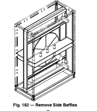
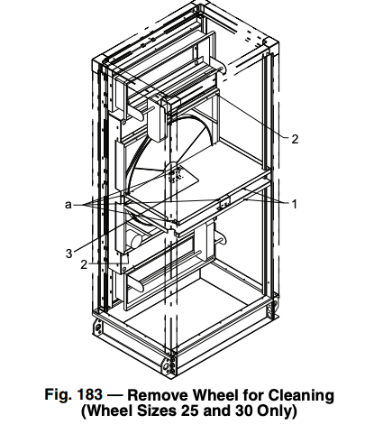
Cleaning the removable segments (wheel sizes 36-104) or the entire wheel (wheel sizes 25 and 30) will remove oil-based aerosols that have condensed on energy transfer surfaces.
To clean removable segments (wheel sizes 36-104):
To clean wheels (size 25 and 30) use this procedure and refer to Fig. 183:
CASSETTE REPLACEMENT
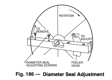
Four adjustable diameter seals are provided on each cassette to minimize air transfer between the counterflowing airstreams.
ADJUSTING AIR SEALS
To adjust diameter seals:
SEGMENT INSTALLATION AND REPLACEMENT
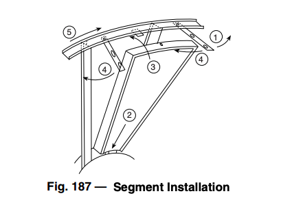
Wheel segments are secured to the wheel frame by a segment retainer, which pivots on the wheel rim and is held in place by a segment retaining catch (Fig. 187).
To install wheel segments follow the steps below and refer to Fig. 187.
WHEEL DRIVE MOTOR AND PULLEY REPLACEMENT
! CAUTION
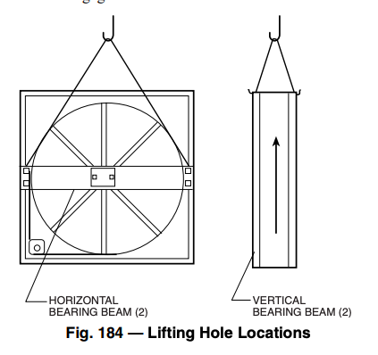
Protect hands and belt from possible sharp edges of hole in bearing support beam.
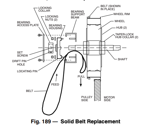
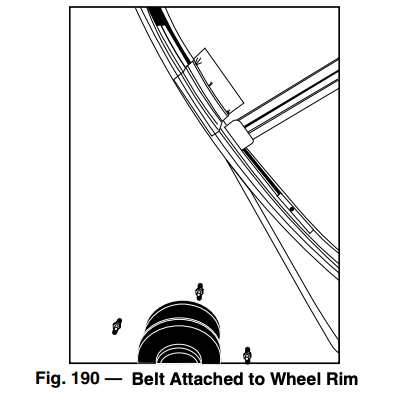
SOLID BELT REPLACEMENT (FIG. 189)
! WARNING
Before performing service or maintenance operations on unit, turn off main power switch to unit. Electrical shock could cause personal injury.
LINK BELT REPLACEMENT
LINK BELT REPLACEMENT
LINK BELT REPLACEMENT
LINK BELT REPLACEMENT
OTHER MAINTENANCE
Wheel drive motor bearings are pre-lubricated and no further lu- brication is necessary
The wheel drive pulley is secured to the drive motor shaft by a combination of either a key or D-slot and setscrew. The setscrew is secured with removable locktite to prevent loosening. Annually confirm that the set screw is secure.
The wheel drive belt is a urethane stretch belt designed to provide constant tension through the life of the belt. No adjustment is re- quired. Inspect the drive belt annually for proper tracking and ten- sion. A properly tensioned belt will turn the wheel immediately af- ter power is applied with no visible slippage during start-up.
Cleaning Unit Interior/Exterior
Unit interior/exterior panels should be wiped down using a damp soft cloth or sponge with a mixture of warm water and a mild detergent. Avoid using an abrasive cleaner, as damage to the paint could occur resulting in rust and corrosion. Chemicals such as paint thinners can damage the painted panels and should be avoided.
! CAUTION
Avoid washing unit electrical devices such as motors, starters, electric heater control boxes, damper/valve actuators, sensors, switches, relays, etc. as serious personal injury or damage to the device could result.
Coil Cleaning
Chilled water, hot water, steam, and direct expansion coils must be cleaned regularly to maintain peak performance. Dirty coils can contribute to loss of cooling or heating capacity and efficiency, increased operating costs, and compressor problems on direct expansion systems. Dirt, grease, and other oils can also reduce the wettability of the coil surfaces, which can result in moisture blowoff from cooling coils and resulting water leakage problems. If the grime on the surface of the coils becomes wet, whi
Coils can become dirty over a period of time, especially if air filter maintenance is neglected. Coils should be inspected regularly and cleaned when necessary. If coil fins become dirty, pressure clean with hot water and detergent or a commercial coil cleaner. Be sure to rinse coils thoroughly after cleaning with chemical cleaners.
! CAUTION
Follow all directions provided with the chemical cleaners to avoid personal injury, injury to others, and/or coil damage. Chemical coil cleaners may contain corrosive or harmful agents.
Winter Shutdown
It is recommended that auxiliary drain piping be added to coil piping if yearly winterizing of coils is anticipated. This auxiliary piping should be located at the highest and lowest point on the respective header connection for each coil.
ANTIFREEZE METHODS OF COIL PROTECTION
Drain coil as follows:
AIR-DRYING METHOD OF COIL PROTECTION
(Unit and coil must be level for this method.)
Coil Removal
NOTE: To reinstall coils, refer to Coil Installation section on page 124.
REMOVAL OF SINGLE HEIGHT COILS (SIZES 03-36)
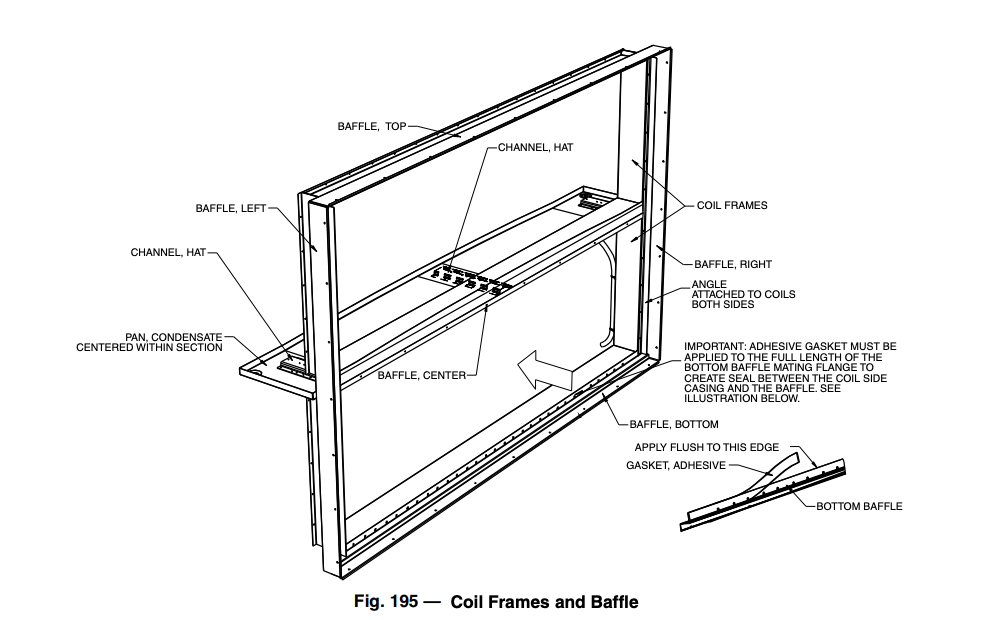
The coils in horizontal coil sections must be removed from either side of the unit. Once the external panels are removed from the unit, the horizontal upper coil section frame members are easily removable from the framework to allow hoisting the coil up and out of the unit.
NOTE: Refer to Table 20 on page 60, (Dry Coil Weights) before attempting to remove a coil from the unit.
IMPORTANT: Properly support the coil to assure its stability before continuing with this procedure.
! CAUTION
Do not handle the coil by the headers or connection nipples, as irreparable damage might occur that is NOT covered by war- ranty. Protect the finned surface from damage during all han- dling and shipping.
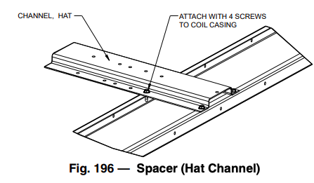
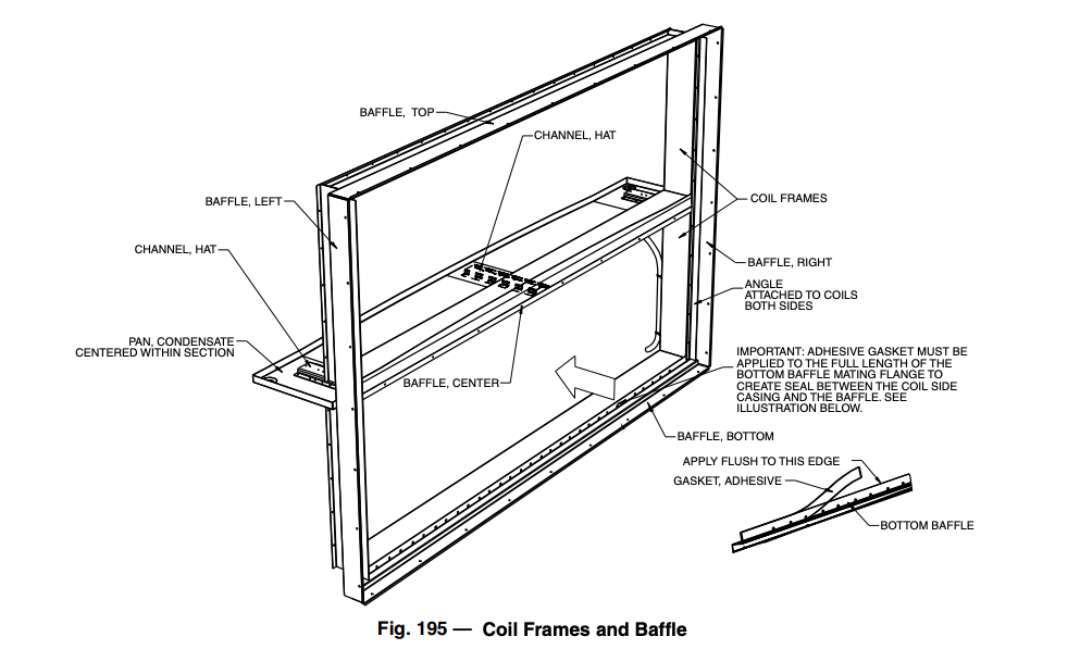
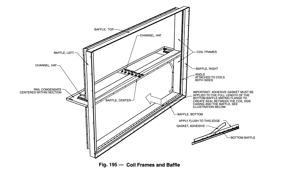
REMOVAL OF STACKED COILS (SIZES 40 TO 110)
The coils in horizontal coil sections must be removed from either side of the unit. Once the external panels are removed from the unit, the horizontal upper coil section frame members are easily removable from the framework, to allow hoisting the coil up and out of the unit.
#2:
#3:
IMPORTANT: Properly support the coil to assure its stability before continuing with this procedure.
! CAUTION
Do not handle the coil by the headers or connection nipples, as irreparable damage might occur that is NOT covered by warranty. Protect the finned surface from damage during all handling and shipping.
! CAUTION
Do not handle the coil by the headers or connection nipples, as irreparable damage might occur that is NOT covered by warranty. Protect the finned surface from damage during all handling and shipping.
Changing Coil Hand
NOTE: Electric heat coil hand cannot be changed.
NOTE: The coil cover panel is not part of the coil. Remove cover panel from end of unit. New holes must be cut in coil cover panel. Original holes must be plugged and insulated. New side panels may be necessary when changing coil hand.
NUFIN COILS
The NuFin coil is airflow direction sensitive, especially when used in dehumidifying applications. Hydronic versions are counterflow circuited for full gravity draining when installed level.
Correct installation will result in the typical bottom inlet on leaving air face and top outlet on entering air face of coil, a self-venting design. This will ensure cold air contact with cold water, and warm air with hot water
Coil repositioning for opposite hand application will compromise one or more of these characteristics. However, there will be those situations where this may prove acceptable.
As a general rule, a change from counterflow circuiting to parallel flow for sensible heating and cooling applications will result in a 5% drop in net capacity per row of coil. In one and two row heating coils, the actual drop may not be measurable, thus of insignificant consequence.
It is important that the airflow direction of the NuFin coil be ad- hered to when latent cooling is possible. Significant moisture car- ryover from the face of the dehumidifying coil will result if this rule is violated, even at very low face velocities. The same result is often experienced if after-market fin coatings are applied.
If a NuFin hydronic coil is installed with correct airflow, but oppo- site piping hand, and counterflow is maintained, steps must be tak- en to ensure that the coil is continuously vented, and that the water velocity is maintained to prevent the coil from air-binding.
Hot or cold areas of the coil face (or otherwise broad temperature differences and stratification) are usually indications that one or more circuits are air-locked internally. This can result in coil freeze-up (a condition NOT covered by warranty).
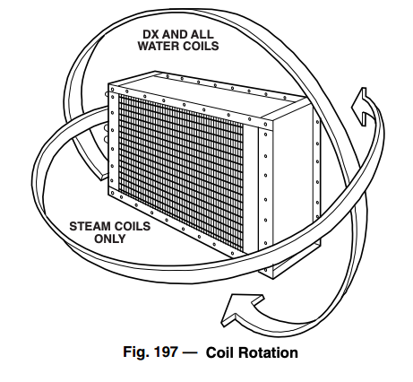
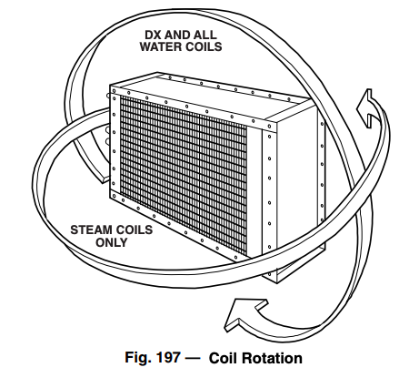
Refrigerant coils may be rotated for opposite hand applications, maintaining the proper airflow direction
Do not reposition the distributor(s); they will perform equally well in upflow or downflow positions. When soldering expansion valves to up-feed distributors, use the minimum satisfactory amount of solder to prevent damaging the valve or plugging passages.
DIRECT EXPANSION COILS
CHILLED WATER AND HOT WATER COILS
STEAM INNER DISTRIBUTING TUBE COILS
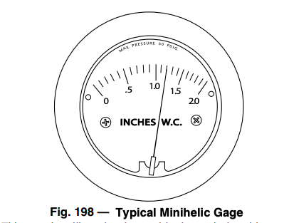
Minihelic Gage
This gage is calibrated and zeroed in the vertical position at the factory. If the gage is used in any other position, it must be re-zeroed each time the position is changed. Gages with ranges under 5 inches w.c. (1.24 kPa), or the equivalent, should be used only in the vertical position.
! CAUTION
Attempted field repair may void your warranty. Recalibration or repair by the user is not recommended.
CALIBRATION CHECK
MAINTENANCE
No lubrication or periodic servicing is required. Keep case exterior and cover clean. Occasionally, disconnect pressure lines to vent both sides of the gage to atmosphere and re-zero the gage.
Source: Carrier (www.shareddocs.com)

