18. WeatherMaker® Single Packaged Rooftop Units 48A: General Maintenance and Cleaning
This procedure is for the general maintenance and cleaning of your Single Packaged Rooftop Units. It focuses on the cleaning, inspection of main burners flue gas passageways to name a few.
18. WeatherMaker® Single Packaged Rooftop Units 48A: General Maintenance and Cleaning
This procedure is for the general maintenance and cleaning of your Single Packaged Rooftop Units. It focuses on the cleaning, inspection of main burners flue gas passageways to name a few.
! WARNING
Before performing service or maintenance operations on unit, turn off main power switch to unit. Electrical shock could cause personal injury.
Service Access
All unit components can be reached through clearly labelled hinged access doors. These doors are not equipped with tiebacks, so if heavy duty servicing is needed, either remove them or prop them open to prevent accidental closure.
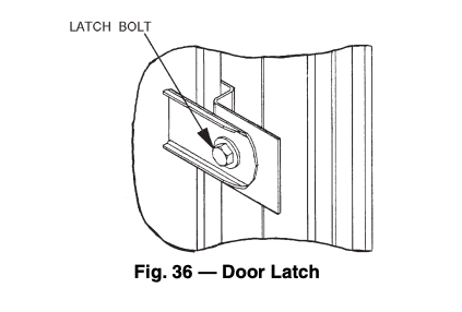
Each door is held closed with 3 latches. The latches are secured to the unit with a single 1/4-in. - 20 x 1/2-in. long bolt. See Fig. 36
To open, loosen the latch bolt using a 7/16-in. wrench. Pivot the latch so it is not in contact with the door. Open the door. To shut, reverse the above procedure.
NOTE: Disassembly of the top cover may be required under special service circumstances. It is very important that the orientation and position of the top cover be marked on the unit prior to disassembly. This will allow proper replacement of the top cover onto the unit and prevent rainwater from leaking into the unit.
IMPORTANT: After servicing is completed, make sure door is closed and relatched properly, and that the latches are tight. Failure to do so can result in water leakage into the evaporator section of the unit.
Cleaning
MAIN BURNERS
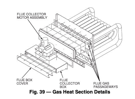
FLUE GAS PASSAGEWAYS
COMBUSTION-AIR BLOWER
To inspect blower wheel:
MICROCHANNEL HEAT EXCHANGER (MCHX) CONDENSER COIL MAINTENANCE AND CLEANING RECOMMENDATIONS
! CAUTION
Do not apply any chemical cleaners to MCHX condenser coils. These cleaners can accelerate corrosion and damage the coil.
Routine cleaning of coil surfaces is essential to maintain proper operation of the unit. Elimination of contamination and removal of harmful residues will greatly increase the life of the coil and extend the life of the unit
The following steps should be taken to clean MCHX condenser coils:
Evaporator Fan Performance Adjustment
Fan motor pulleys are designed for speed shown in Physical Data table in unit Installation Instructions (factory speed setting).
IMPORTANT: Check to ensure that the unit drive matches the duct static pressure using Tables 3-38.
To change fan speeds, change pulleys.
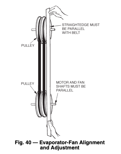
To align fan and motor pulleys:
Evaporator Fan Coupling Assembly
If the coupling has been removed for other blower assembly component repair or replacement, it is critical that the coupling be reassembled and aligned correctly to prevent premature failures.
REASSEMBLING THE COUPLING INTO THE UNIT
Evaporator Fan Service and Replacement
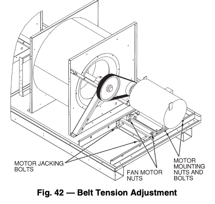
Belt Tension Adjustment
To adjust belt tension:
Evaporator-Fan Motor Replacement
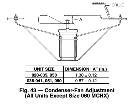
NOTE: Condenser fans on size 060 MCHX units are not adjustable.
Condenser-Fan Adjustment
Four-Inch Filter Replacement: The 4-Inch Filter Change Mode variable is used to service the unit when 4-in. filters are used. When the filters need to be changed, set Service TestF.4.CH = YES. The unit will be placed in Service Test mode and the economizer will move to the 40% open position to facilitate removal of the 4-in. filters. After the filters have been changed, set Service TestF.4.CH = NO to return the unit to normal operation.
Power Failure: The economizer damper motor is a spring return design. In event of power failure, dampers will return to fully closed position until power is restored.
Refrigerant Charge
Amount of refrigerant charge is listed on unit nameplate. Refer to Carrier GTAC II; Module 5; Charging, Recovery, Recycling, and Reclamation section for charging methods and procedures.
Unit panels must be in place when unit is operating during charging procedure.
NOTE: Do not use recycled refrigerant as it may contain contaminants.
NO CHARGE
LOW CHARGE COOLING
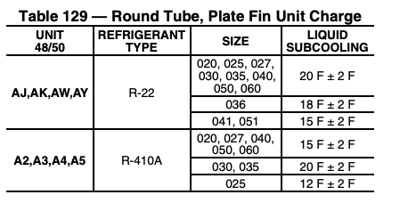
All Units with Round Tube-Plate Fin Condenser Coils
48/50A2,A3,A4,A5 Units with MCHX Condenser
Due to the compact, all aluminum design, microchannel heat exchangers will reduce refrigerant charge and overall operating weight. As a result, charging procedures for MCHX units require more accurate measurement techniques.
Charge should be added in small increments. Using cooling charging charts provided (Fig. 44-50), add or remove refrigerant until conditions of the chart are met. As conditions get close to the point on the chart, add or remove charge in 1/4 lb increments until complete. Ensure that all fans are on and all compressors are running when using charging charts.
To Use the Cooling Charging Chart:
Use the outdoor air temperature, saturated suction temperature and saturated condensing temperature (available on the ComfortLink display), and find the intersection point on the cooling charging chart. If intersection point is above the line, carefully recover some of the refrigerant. If intersection point is below the line, carefully add refrigerant.
NOTE: Indoor-air cfm must be within normal operating range of unit.
Thermostatic Expansion Valve (TXV)
— Each circuit has a TXV. The TXV is adjustable and is factory set to maintain 8 to 12° F superheat leaving the evaporator coil. The TXV controls flow of liquid refrigerant to the evaporator coils. Adjusting the TXV is not recommended.
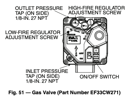
Gas Valve Adjustment
NATURAL GAS
The 2-stage gas valve opens and closes in response to the thermostat or limit control.
When power is supplied to valve terminals 3 and 4, the pilot valve opens to the preset position. When power is supplied to terminals 1 and 2, the main valve opens to its preset position.
The regular factory setting is stamped on the valve body (3.5 in. wg).
To adjust regulator:
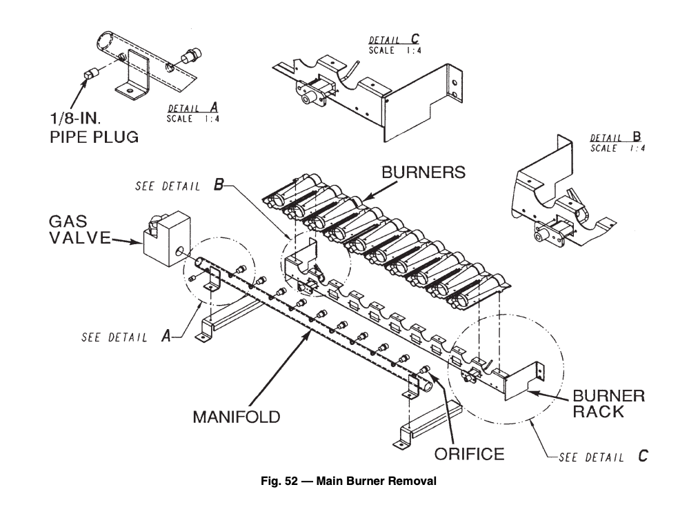
Main Burners
For all applications, main burners are factory set and should require no adjustment.
MAIN BURNER REMOVAL (Fig. 52)
Filter Drier — Replace whenever refrigerant system is exposed to atmosphere.
Replacement Parts — A complete list of replacement parts may be obtained from any Carrier distributor upon request.
Source: Carrier (www.shareddocs.com)

