2015 HYSTER S40FT CUSHION TIRE 4 WHEEL SIT DOWN FORMS (Daily Maintenance)
The 2015 HYSTER S40FT CUSHION TIRE 4 WHEEL SIT DOWN Daily Maintenance Form ensures your equipment is running properly, avoiding costly downtime and extending the life cycle of the equipment. Ultimately, this form helps you save time and money.
Tires and Wheels
Remove material that is wrapped around the axle.
Figure 32. Check the Tires
SAFETY LABELS
WARNING
MAST, CARRIAGE, HEADER HOSES, LIFT CHAINS, AND ATTACHMENT
(See Figure 47 and Figure 33)
WARNING
Lower the lift mechanism completely. Never allow any person under a raised carriage. Do not put any part of your body in or through the lift mechanism unless all parts of the mast are completely lowered and the engine is STOPPED.
Do not try to correct the alignment of the fork tips by bending the forks or adding shims. If either fork is damaged, replace the forks as a set.
Never repair damaged forks by heating or welding. Forks are made of special steel using special proce- dures. If either fork is damaged, replace the forks as a set.
Inspect the welds on the mast, cylinders, and carriage for cracks. Make sure that the cap screws and nuts are tight.
Inspect the channels for wear in the areas where the roll- ers travel. Inspect the rollers for wear or damage.
Inspect the load backrest extension for cracks and damage.
If the lift truck is equipped with a side shift carriage or attachment, inspect the parts for cracks and wear. Make sure the parts that fasten the sideshift carriage or attachment to the carriage are in good condition.
Visually inspect hoses/fittings for hydraulic leaks;
hose cover for cuts
cracks
exposed reinforcement
defective/ broken clamping devices or sheaves
proper tracking during operation
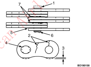
Figure 33. Lift Chain Check
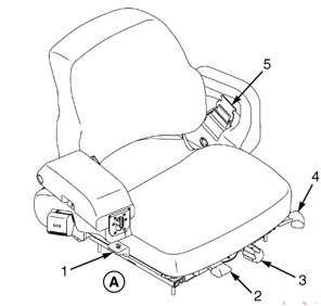
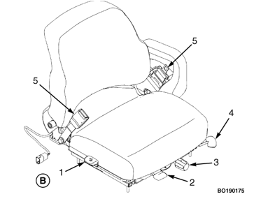
Figure 34. Hood and Seat Check
Legend for Figure 34
NOTE: NON-SWIVEL SEAT SHOWN.
A. AUTOMATIC LOCKING RETRACTOR
B. EMERGENCY LOCKING RETRACTOR
SEAT BELT, HIP RESTRAINTS AND SEAT RAILS
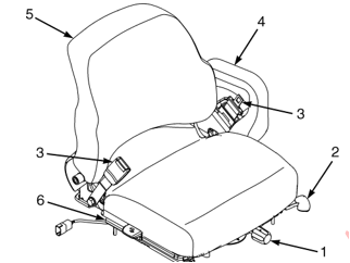
Figure 35. Hood and Seat Check
NOTE: NON-SWIVEL SEAT SHOWN.
Automatic Locking Retractor (ALR)
NOTE: S40-70FT, S55FTS lift trucks produced before November 1, 2005 are equipped with the ALR type seat belts. See Figure 36
Figure 36. Seat Belts
HOOD AND SEAT LATCHES
AUTOMATIC LOCKING RETRACTOR
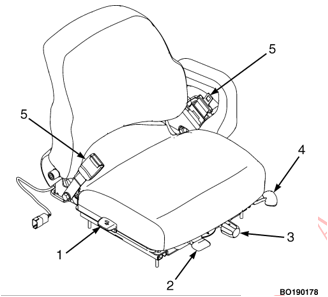
NOTE: SWIVEL SEAT IS AN OPTIONAL FEATURE.
B. EMERGENCY LOCKING RETRACTOR
ENGINE COMPARTMENT
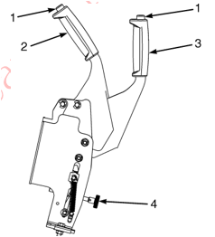
Figure 37. Swivel Seat Controls
NOTE: SWIVEL SEAT IS AN OPTIONAL FEATURE.
Paper Application
WARNING:Engine and exhaust system components are hot to the touch. Be sure lift truck components are cool before starting inspection and cleaning, or personal injury may occur.
Check engine, Clean as required
Check and clean
WARNING: Compressed air can move particles so that they cause injury to the user or to other personnel. Make sure that the path of the compressed air is away from all person- nel. Wear protective goggles or a face shield to prevent injury to the eyes.
CAUTION: Air pressure, nozzle, or extension tube may cause damage to exhaust wraps and radiator fins. Assure that air pressure, nozzle, or extension tube does not dam- age exhaust wraps or radiator fins.
WARNING: Be careful when cleaning with steam. Steam can cause serious burns. Wear protective clothing, gloves, and eye protection. Never expose your skin to steam.
Check the condition of exhaust
CHECK FOR LEAKS - FUEL, OIL, WATER
WARNING: All fuels are very flammable and can burn or cause an explosion. Do not use an open flame to check the fuel level or to check for leaks in the fuel system. If there is a leak in the fuel system, extra care must be used dur- ing the repair. Do not
HYDRAULIC HOSES
COOLANT HOSES
FUEL TANK (GAS) S40-70FT, S55FTS (F187)
FUEL TANK (GAS) H40-70FT (L177)
FUEL TANK (LPG)
FUEL TANK (DIESEL) H40-70FT (L177)
Indicator Lights, Horn, Fuses, and Relays
SERVICE BRAKES
Brake Fluid Level
WARNING: Small amounts of water in the brake system can cause reduced braking performance if the water reaches the wheel cylinder area. Do not allow water entry, ensure that the sealed reservoir lid is properly replaced.
If the brake system has a power assist (or boost), brak- ing will be more difficult if the engine is not running.
On lift trucks with wet brake drive axles, only use Dex- ron III oil from sealed container in the master cylinder. On lift trucks with dry brake drive axles, only use SAE J-1703 (DOT 3) brake fluid in the master cylinder.
Loss of fluid from the brake fluid reservoir indicates a leak. Repair the brake system before using the lift truck. Replace the brake fluid in the system if there is dirt or water in the system.
Failure to observe the above warnings could result in death or serious injury.
Lift trucks with a pedal
Parking Brake
Lift trucks with a pedal:
NOTE: Make sure parking brake is released before making adjustment.
To adjust the parking brake, do the following:
Figure 49. Parking Brake Adjustment
STEERING CONTROLS AND STEERING COLUMN GAS CYLINDER
Figure 39. Steering Column Gas Cylinder and Tilt Lever
Transmission
Check the transmission for :
HYDRAULIC OIL S40-70FT, S55FTS (F187)
HYDRAULIC OIL H40-70FT (L177)
HYDRAULIC OIL FILTER
WARNING: At operating temperature the hydraulic oil is HOT. Do not permit the hot oil to touch the skin and cause a burn.
CAUTION :Do not permit dirt to enter the hydraulic system when the oil level is checked or the filter is changed. Never operate the hydraulic pump without oil in the hydraulic system. The operation of the hydraulic pump without oil will damage the pump.
HYDRAULIC TANK BREATHER
BATTERY AND CABLE TERMINALS
CAUTION: DO NOT try to start the engine by pushing or towing the lift truck. Damage to the transmission can occur if engine is started by pushing or towing lift truck.
If the battery becomes discharged and requires a booster battery to start the engine, follow these procedures care- fully when connecting the jumper cables:
ENGINE OIL Mazda 2.0L Engine (Gas/LPG)
ENGINE OIL Mazda 2.2L Engine (Gas/LPG)
ENGINE OIL GM 2.4L Engines (Gas/LPG)
ENGINE OIL FILTER Mazda 2.0L and 2.2L and GM 2.4L Engines
ENGINE OIL Yanmar 2.6L and 3.3L Engines (Diesel)
ENGINE OIL FILTER Yanmar 2.6L and 3.3L Engines (Diesel)
Engine Oil
Figure 40. Mazda 2.0Land 2.2L Engine Maintenance Points (Except 2007 Emission Compliant Engines)
A. GAS ENGINE
B. LPG ENGINE
Figure 41. Mazda 2.0Land 2.2L Engine Maintenance Points (2007 Emission Compliant Engines Only)
A. LPG ENGINE
B. GAS ENGINE
Figure 42. GM Engine Maintenance Points
A. GAS ENGINE
B. LPG ENGINE
Figure 43. Yanmar 2.6L and 3.3L and 3.3L Diesel Engine Maintenance Points
AIR FILTER
The air filter canister should not be opened until an air filter element replacement is required. An air filter element replacement is required when one of the following occurs:
Do not operate the lift truck until the air filter element has been replaced.
COOLING SYSTEM
COOLING SYSTEM
COOLING SYSTEM
COOLING SYSTEM
FORKS
NOTE: Forks must be removed or installed by trained per- sonnel only.
The identification of a fork describes how the fork is con- nected to the carriage. These lift trucks have hook forks.
Forks, Remove
NOTE: If lift truck is equipped with a fork positioner attach- ment, perform Step 1 first, before going to Step 2. If lift truck is not equipped with a fork positioner attachment, go to Step 2.
Figure 44. Fork Positioner
WARNING: Do not try to move a fork without a lifting device. Each hook fork for these lift trucks can weigh 45 to 115 kg (99 to 253 lb).
NOTE: Forks are to be replaced only in sets and not indi- vidually.
Figure 45. Remove a Hook Fork
Figure 46. Fork Lock Pin Assembly
Forks, Inspect
Forks, Install
Forks, Adjust
NOTE: During the adjustment of the forks, the heel of the forks should not be touching the ground.
Figure 47. Forks Check
MAST
BRAKE FLUID
WARNING :Small amounts of water in the brake system can cause reduced braking performance if the water reaches the wheel cylinder area. Do not allow water entry, ensure that the sealed reservoir lid is properly replaced. If the brake system has a power as
On lift trucks with wet brake drive axles, only use Dex- ron III oil from sealed container in the master cylinder. On lift trucks with dry brake drive axles, only use SAE J-1703 (DOT 3) brake fluid in the master cylinder.
Loss of fluid from the brake fluid reservoir indicates a leak. Repair the brake system before using the lift truck. Replace the brake fluid in the system if there is dirt or water in the system. Failure to observe the above warnings could result in death
BRAKE OIL
Source: Hyster

