Cleaver Brooks Model 5 750-154 FLX Maintenance
Cleaver Brooks Model 5 750-154 FLX Maintenance
Water Level Controls
Water Gauge Glass
Operating Controls
Setting and Adjusting
Burner Operating Controls: Gas
Burner controls properly set to match load demands will provide operational advantages and achieve the following desirable objectives:
Operating and Modulating Control Actions
Pressure Controls: Steam Boiler (Oil)
Temperature Controls: Hot Water Boiler (Oil)
Relative settings of the temperature controls are as follows:
High Limit Control
Operating Limit Control
High-Low Fire Control (high fire)
Operating LImit Pressure Control (Steam)
(Honeywell L404A)
High Limit Pressure Control (Steam)
(Honeywell L404C)
High-Low Fire Control (Steam)
(Honeywell L404A)
Modulating Pressure Control (Steam)
(Honeywell L91A)
Turn adjusting screw until the indicator is opposite the low point of the desired modulating range. Modulated firing will range between this point and a higher point equal to the modulating range of the particular control.
NOTE: To prevent burner shutdown at other than low fire setting, adjust modulating pressure control to modulate to low fire before operating limit pressure control shuts off burner.
Operating Limit Temperature Control (Hot Water)
(Honeywell L4008A)
High Limit Temperature Control (Hot Water)
(Honeywell L4008E)
Low Fire Hold Timer
System Low Pressure Control
High-Low Fire Control (Hot Water)
(Honeywell L4008A)
Modulating Temperature Control (Hot Water)
(Honeywell T991A)
NOTE: To prevent burner shutdown at other than low fire setting, adjust modulating temperature control to modulate to low fire before operating limit temperature control shuts off burner.
Control Operational Test (Oil)
Combustion Air Proving Switch
(Honeywell C645A)
Programming Control
Caution: When replacing the control, or cleaning contacts, be sure to open the main power supply switch, since the control is “hot,” even though the burner switch is off.
Low Gas Pressure Switch
(Honeywell C437A)
High Gas Pressure Switch
(Honeywell C437B)
Low Oil Pressure Switch (Optional)
Oil Burner
FIGURE 5-2. Oil Burner Drawer: Spark Ignition
FIGURE 5-3. Burner Drawer: Gas Pilot Ignition
Diffuser
Burner Nozzles
FIGURE 5-4. Nozzle Sizes, Location, and Firing Rate
NOTE: Nozzle size is rating at 100 psi oil pressure. Flow rate increases with pressure. Multiply boiler size by 1000 to obtain maximum input BTU/HR.
Ignition System
Oil Pump Belt
Oil Pump
Combustion Adjustment (Oil)
Gas Burner
Overview
Gas Pilot Flame Adjustment
To measure and adjust the pilot:
NOTE: On an initial starting attempt, portions of the fuel lines may be empty and require “bleeding” time. It is better to accomplish this with repeated short lighting trial periods with intervening purge periods than to risk prolonged fuel introduction.
! Caution: Keep eyes sufficiently away from the sight tube opening and wear a protective shield or suitable glasses. NEVER remove the flame detector while the main burner is firing.
Gas Input
Gas Fuel Combustion Adjustment
FIGURE 5-5. Flue Gas Analysis Chart for Natural Gas
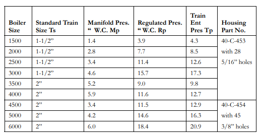
From information in this chapter, determine the standard conditions of gas pressure and flow for the size of boiler and the gas train on it
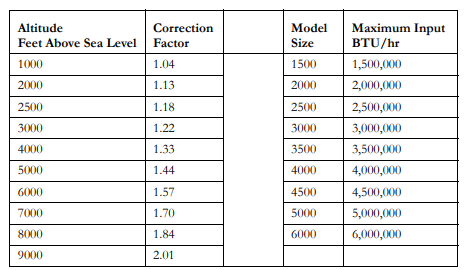
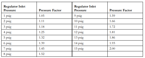
Calculate the actual pressure and flow through the use of correction factors that compensate for incoming gas pressure and altitude.
In initially setting the linkage:
FIGURE 5-6. Butterfly Gas Valve
This low fire setting should be regarded as tentative until proper gas pressure for high fire operation is established. To do this:
Flow rate is highest when the cam follower assembly is closest to the jack-shaft.
FIGURE 5-7. Gas Modulating Cam
Checking Gas Flow
Lacking a chart of this nature, it is possible to “clock the meter”:
Use the following formula to provide the required gas input for a 3 minute period:
Pressure Correction
Combustion Efficiency (Gas)
Air Damper Adjustment
The arms and connecting rod that transmit motion from the damper motor to the air damper (and to the gas butterfly valve on a gas fired unit) are set at the factory and should not normally need further adjustment.
If adjustments are required, or to aid in determining the position of linkage in event of replacement, the following factors should serve as guides:
Normally, at low fire the damper blade is cracked slightly open. With the burner firing at its low rate, hold the damper shaft securely with pliers and loosen the setscrew on its arm.
Manually close the damper until a slight haze appears and then open until it clears. Tighten setscrews and for reference purposes mark the position of the shaft slot to indicate approximate low fire damper setting.
NOTE: As pointed out in the sections pertaining to combustion adjustment, color is a poor indication of flame efficiency and should be used only for tentative adjustment. Final adjustments should be made based upon stack analysis and with proper fuel inpu
Forced Draft Fan
Cam Adjustment
Fuel Valves: Gas and Pilot Main: Gas
Caution: Never operate your boiler with a fuel or pilot valve that is known to be or suspected to be leaking.
Flame Safeguard Check (All Series)
Checking Gas Pilot
Failure to Light Main Flame
NOTE: If the oil burner has direct spark ignition, there will be no flame during the pilot ignition period, and relay 2K will not be energized. The safety switch will lock out approximately 30 seconds after the trial for pilot ignition.
Loss of Flame
Safety and Relief Valves
Refractory
Source: Cleaver Brooks


