Mack | Mack E-Tech Engine - Regular Maintenance
Use this checklist for the cleaning and inspection of your unit injector. Regular maintenance helps in preserving your truck and ensuring that it performs at its best for a long period of time.
Mack | Mack E-Tech Engine - Regular Maintenance
Use this checklist for the cleaning and inspection of your unit injector. Regular maintenance helps in preserving your truck and ensuring that it performs at its best for a long period of time.
BELT DRIVE SYSTEM TENSIONING
[216]
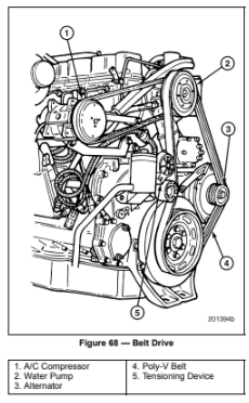
The belt drive system uses a single, 10-rib poly-v belt to drive the alternator, water pump, and fan drive. A separate single-v belt, running off the water pump pulley, drives the refrigerant compressor. The service life of the poly-v belt is considerably improved over other systems and allows the use of higher horsepower cooling fans. Refer to Figure 68.
Both manually tensioned and automatically tensioned systems are used. Whether an engine has the manually tensioned or automatically tensioned system depends on the specific engine configuration and application. The following service information covers both systems.
Manually Tensioned System
INSTALLATION
Loosen the alternator mounting bolts and pivot the alternator inboard, far enough to allow the belt to be placed over the pulleys without force. Do not pry the belt over a pulley.
TENSIONING
Using a belt tension gauge, such as J 41251-B from Kent-Moore, check the belt tension at the widest span between pulleys. Adjust belt tension according to the following specifications:
MAINTENANCE
The belt tension and condition of the belt should be checked when performing preventive maintenance inspections A, B, C and D as outlined in the Maintenance and Lubrication manual, TS494. Belts should be tightened when needed, using the procedures described in this manual.
Automatically Tensioned System
INSTALLATION
Swing the tensioner to the fully sprung position and, without force, place the belt over the pulleys. Do not allow the tensioner to snap against its stops. Do not pry the belt over a pulley.
TENSIONING
No tensioning adjustment is required. Once the tensioner is released against the belt, the belt is tightened to optimum tension automatically at all speeds and loads.
MAINTENANCE
The condition of the belt and tensioner should be checked when performing preventive maintenance inspections A, B, C and D as outlined in the Maintenance and Lubrication manual, TS494. Belt tension level need not be checked as long as tensioner is in good condition and there is no evidence of a loose belt.
FILTER ELEMENT REPLACEMENT
General Information
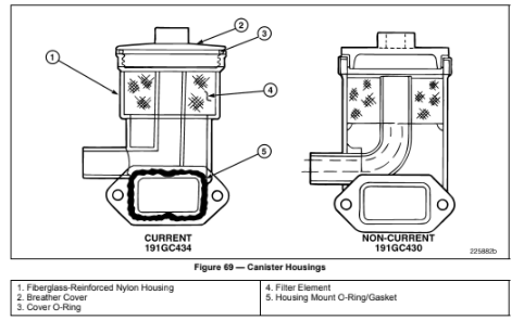
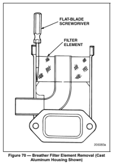
The engine may be equipped with either a cast aluminum or fiberglass-reinforced nylon crankcase breather filter canister as shown in Figure 69. Regardless of the canister style, the breather filter element can be cleaned if it has become plugged following the procedure in this section.
Crankcase Breather Filter Cleaning
[219 ER]
Oil Filter Element Replacement
[219 EV]
SPECIAL TOOLS REQUIRED
GENERAL INFORMATION
Two different oil filter mounting adapter designs are used, one for engines with the removable bundle-type oil cooler and another for engines with the plate-type cooler.
Engines with removable bundle-type oil coolers
The plunger-style oil filter bypass relief valve used in early production oil filter mounting adapters was replaced with a poppet- style valve in November 1997 (beginning with engine serial number series 7V). With this change, the oil filter mounting adapter was redesigned to accommodate the poppet-style relief valve and to eliminate the section that contained the plunger-style valve. When performing an oil and filter change, it is suggested that functionality of the poppet-style relief valve be checked b
Engines with plate-type oil coolers
The oil filter mounting adapters on these engines are also fitted with the poppet-style valve. Again, the functionality of the poppet-style relief valve can be checked by pushing against the viton disk to verify spring tension each time the oil and filters are replaced.
Centri-Max® filter assemblies
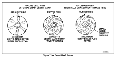
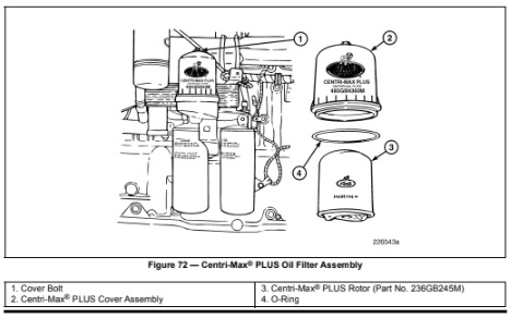
There are different style rotors used in both the externally drained and internally drained Centri-Max® assemblies. As such, it is important that the proper rotor be used in the Centri-Max® unit for which it was designed.
From the inception of the Centri-Max® filter assembly (externally drained), the rounded end of the original rotor (part No. 236GB244A) had several straight ribs radiating from the center of the rotor, like spokes of a wheel.
Effective September 1998, a more efficient “swept” rotor (part No. 236GB244B) was implemented into production. The swept rotor is easily identified by the ribs on the rounded end, which are now curved rather than straight.
The Centri-Max® PLUS (internally drained) unit also uses the swept rotor design, but the bushings in each end of the rotor are of a smaller inside diameter to fit over the smaller diameter spindle used with the internally drained configuration. This rotor (part No. 236GB245M) must be used with the Centri-Max® PLUS filter. If either of the other two rotor part numbers are used, they will be loose on the spindle and will not rotate. If the rotor does not rotate, the centrifugal filter will not function. The C
DISPOSABLE SPIN-ON OIL FILTER REPLACEMENT
Change oil and replace oil filters using the following procedure:
Note: Use of anything other than genuine MACK filters may cause damage and void the engine warranty. Change filters according to the recommended maintenance schedule.
CENTRI-MAX® FILTER REPLACEMENT
(Externally Drained Filter)
Caution: Be sure to apply the filter removal tool on the filter housing at the point marked “WRENCH HERE.”
CENTRI-MAX® PLUS FILTER REPLACEMENT (Internally Drained Filter)
Caution: Use only the rotor designed for use with the Centri-Max® PLUS centrifugal filter assembly. Any other rotor will not work.
CENTRI-MAX® PLUS SPINDLE REPLACEMENT
[219 EV]
Normally, it should never be necessary to replace the Centri-Max® PLUS rotor spindle. However, if the spindle is damaged in any way, replacement procedures are as follows:
Fuel Filter Replacement
[224 KP, 231 PV]
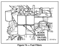
GENERAL INFORMATION
Attempting to install E7 filters with English threads on an E-TechTM engine (that has metric threaded spuds) will cause the following to occur:
Primary Filter — The diameters of the filter threads and the threaded spud are close in size. Although the filter can be started on the spud threads using force, the threads will be damaged.
Secondary Filter — The diameter of the filter threads is smaller than the diameter of the threaded spud. Consequently, the filter cannot be installed.
Attempting to install E-TechTM filters (with metric threads) on an E7 engine with English threads would not result in damage to the threads. The diameters of the filter threads are large enough to prevent installation of the filters.
REPLACEMENT PROCEDURE
Install fuel filters using the following procedure.
Note: Use of anything other than genuine MACK filters may cause damage and void the engine warranty. Change filters according to the recommended maintenance schedule.
Note: If the engine fails to start after installing new fuel filters, refer to Priming the Fuel System under Engine Final Preparation and Operational Check.
Coolant Conditioner Replacement
[125 LD]
If the engine is equipped with the optional coolant conditioner, the conditioner element is replaced as follows:
Source: MaintainX (Community Member)

