Back

Lennox CB17/CBH17-95/135/185/275 Blower Coils: Maintenance

This maintenance procedure and service must be performed by a qualified installer or service agency. This procedure focuses on checking your equipment's outdoor unit, how to clean and inspect the outdoor coil. Following the recommended maintenance procedure will help you maintain the superior efficiency of your unit for a long period of time.
MaintainX
10/24/2021

Lennox CB17/CBH17-95/135/185/275 Blower Coils: Maintenance

This maintenance procedure and service must be performed by a qualified installer or service agency. This procedure focuses on checking your equipment's outdoor unit, how to clean and inspect the outdoor coil. Following the recommended maintenance procedure will help you maintain the superior efficiency of your unit for a long period of time.

    Adjusting Belt Tension

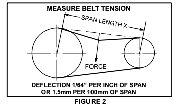
    Maximum life and wear can only be obtained from belts if proper pulley alignment and belt tension are maintained. Initially tension new belts at the maximum deflection force recommended (1/64 inch per inch of span), and then re− tension belt after 24−48 hour run period. This allows belt to stretch and seat in grooves.

    To remove or tension belt, loosen the bolts on the hinged motor cradle and slide up or down.

    Check Belt Tension

    Overtensioning belts shortens belt and bearing life. Check belt tension as follows:

    • Screenshot2021-02-19at8.47.43AM.png

    REFRIGERATION SYSTEM

    The coil is divided into two sections. The lower portion is first stage and the upper section is second stage. Each section has its own liquid line connection and expansion valve or valves. This configuration allows the use of a solenoid valve to control the flow of refrigerant into one coil section. Use this feature for capacity reduction or latent heat control. If a solenoid valve is used, install it directly ahead of the expansion valve of the coil section being controlled. Size the solenoid valve for ap

    The expansion valves are sized specifically for the two stages. The CB17/CB17H−95−2 units have 4 ton first stage expansion valves and 3 ton second stage valves. The CB17/CB17H−135−2 units have 5 ton first stage expansion valves and 4 ton second stage valves. The CB17/CB17H−95−3 units have 6 ton first stage expansion valves and 4 ton second stage valves. The CB17/CB17H−135−3 units have 6 ton first stage expansion valves and 4 ton second stage valves.

    The CB17/CBH17−185 has a 7−1/2−ton first− and second− stage expansion valve. The CB17/CBH17−275 has two 5−ton first− and two 5 ton second−stage expansion valves.

    Refrigerant lines or stubbed for sweat connections and are located inside the unit cabinet. See figure 1.

    CONDENSATE PAN

    Two drain outlets are provided, one per side. Never connect condensate drain to a closed system. Condensate drain line must have a trap in the line at the unit exit.

Please note that any procedure, checklist, or other document available in the MaintainX Procedure Hub is provided for general education and information only and does not constitute legal, medical, or financial advice. MaintainX makes the materials available AS IS and AS PROVIDED, without warranties of any kind. By downloading or using any such materials, you assume the risk that they may not be appropriate for your specific situation and agree that you are solely responsible for any such use, including compliance with applicable law and with meeting any conditions of product warranties.