BARBARIC STORAGE SYSTEM CSF
MAINTENANCE INSTRUCTIONS STORAGE SYSTEM CSF
BARBARIC STORAGE SYSTEM CSF
MAINTENANCE INSTRUCTIONS STORAGE SYSTEM CSF
These maintenance instructions describe the system and its individual components. It will help you operate the system cost-efficiently and economically. Furthermore, it provides useful instructions for maintenance as well as safety instructions for maintenance as well as safety instructions during maintenance. In accordance with the operating experience of Barbaric GmbH, it is necessary to check the system regularly and identify the defective parts, which must be replaced timely in order to avoid consequential damages and downtimes. SAFETY INSTRUCTIONS DANGER indicates an imminent dangerous situation, which, if not avoided, may result in death or severe injuries. WARNING indicates a possibly dangerous situation, which, if not avoided may result in death or severe injuries. CAUTION indicates a possibly dangerous situation, which, if not avoided, may cause minor or serious injuries. DANGER high voltage indicates Electrical dangers are possible, if instructions were not followed properly. NOTE Signal word for a possibly unwanted event or condition, which might occur, if this situation is not avoided. signal word for a procedure, which will protect from injuries. WARNING- The storage system CSF and all related products have been developed and manufactured under the highest standards of working experience and materials. Therefore, all applicable industry standards were followed. The product shall only be used after providing instructions and training to the operating staff. Improper use may cause injuries or material damages. If the storage system CSF show any signs of malfunction or fatigue, it is not allowed to perform any operations. The storage system must be repaired before operations. Qualifications and Staff: The staff responsible for operations, maintenance, inspection and installation must be suitable qualified for this work. If the staff does not possess appropriate knowledge, it has to be trained and instructed. Additionally, the operator has to ensure that the content of the operating instructions has been fully understood by the staff. NOTE: It is recommended to leave maintenance and cleaning works to the operating staff. As production staff is permanent on site, it will have a better understanding of the system and its behavior. Therefore it will be capable to react to any change at an early stage. Dangers due to non-compliance with safety instructions: Non-compliance with safety instructions may endanger life, environment or system. Non-compliance with safety instructions may cause a loss of justification for damage claims. Non-compliance may cause: - Serious system malfunction. - Threat to life resulting from electrical and mechanical influences. - Risk of injuries or material damages. Safety Awareness: It is necessary to follow: -Safety instructions included in the maintenance instructions. -Threat to life resulting from electrical and mechanical influences. -Risk of injuries or material damages. Safety Instructions for the Operator: -Do not remove the contact protection for moving parts when the system is operating. -Do not hang any item on the product. Any other accessory part must be a stable fit or permanently attached. -Do not climb on the system. -Do not remove or paint over type plates, warnings, notes or any other labels or the system. Safety Instructions for Maintenance and Inspection: The storage system must be placed out of order when performing service or repair works on it. Once the work has been completed, immediately place back or turn on every component of the safety and protection equipment. Illegal Reproduction, Production, and Use of Spare Parts: Reproducing or modifying the product is only allowed after consulting the manufacturer. Original spare parts and accessory parts, which are approved by the manufacturer, ensure safety. The use of non-original spare parts or accessory components may void all damage claims. It is not allowed to use any component of the manufacturer with products supplied by other manufacturer may void all damage claims.
SYSTEM INFORMATION
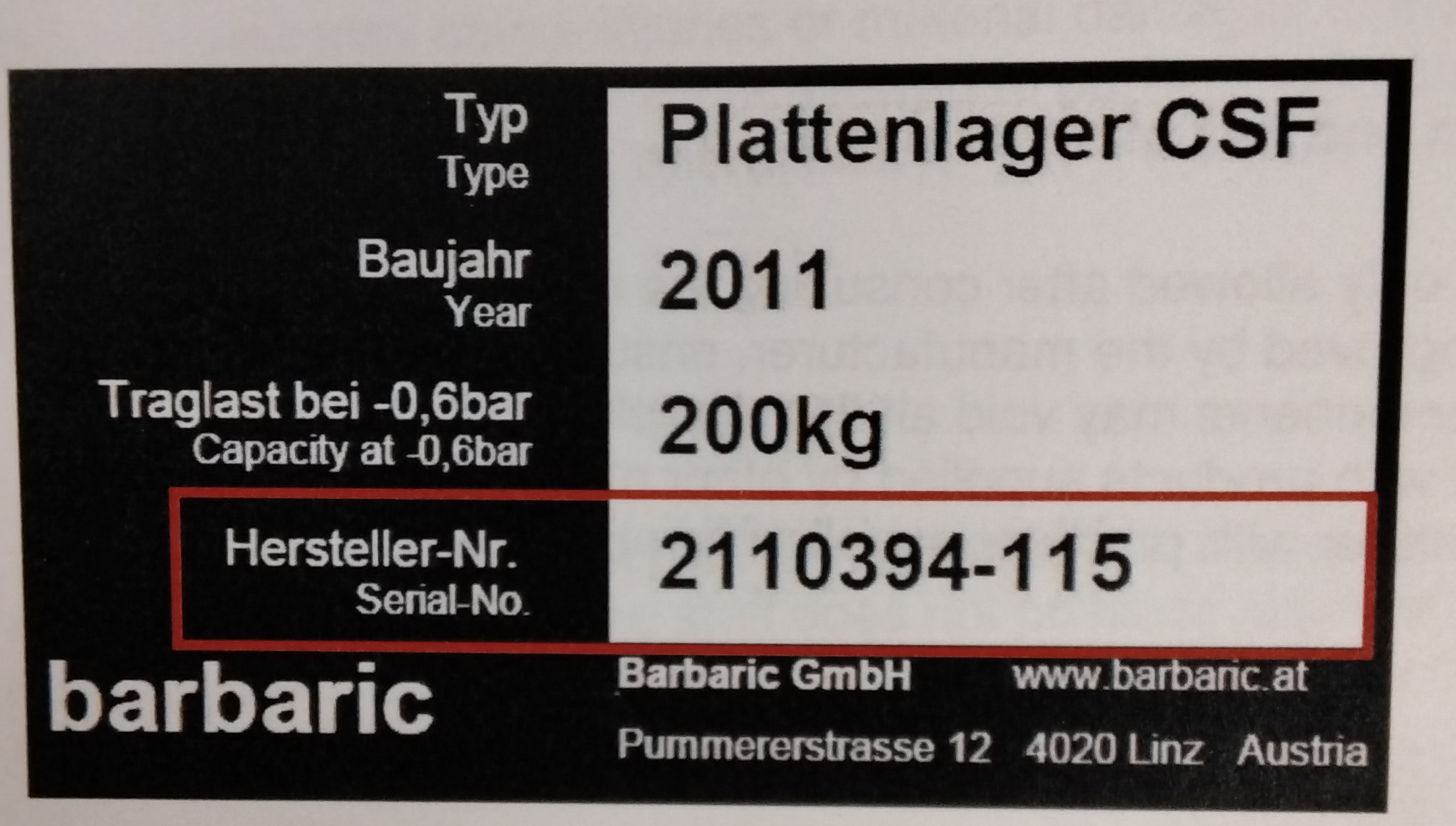
TYPE PLATE: When ordering spare parts or in case of any requests or questions about the storage system, pleas supply your serial number! TECHNICAL DATA: Length of whole system - see layout Width of whole system - see layout Height of whole system- see layout. Maximum panel weight- see layout POWER INPUT: Voltage: 400V Frequency: 50Hz Control Voltage: 24V DC Wire Cross Section: 5X4mm squared Ground wire: 10 mm squared Power: 8kW (3-phase); 5kW (1-phase) Fuse: max. 25A Air consumption: max 900 NI/min Air pressure: min 6 bar Air connection: push in Quality class: 3 (ISO 8573-1) ADMISSABLE ENVIRONMENTAL INFLUENCES Environmental temperature: min. +10 degrees C max. +35 degrees C Humidity: min 20% max. 80% non-condensing MAINTENANCE INTERVALS The following intervals are recommended: - monthly visual inspection of the manipulator and the system - Annual maintenance: single-shift operation - Biannual maintenance: Two-shift operation.
MAINTENANCE
WARNING! Only qualified staff is allowed to perform maintenance works. WARNING! Before performing service works on drives of all kinds, valves and any other components of the system, make sure no electrical power is switched on (compressed air, electricity) In order to optimize availability of system and safety, operators must be trained accordingly and capable of performing low maintenance works. Partially supplemented with graphics, the following description will provide instructions for the operating staff where to perform which activity. The operator of the system is responsible that operating staff has been trained properly in order to operate and control the system. Protocols about who has been trained or operating the system to logged and taken down in the system documentation. Tidiness/Cleaning: Lacquer damages should be repaired annually. In general, the system and the areas of the system have to be cleaned and tided up regularly. Note: Only a clean system may guaranteed proper operations.
STEEL WORK
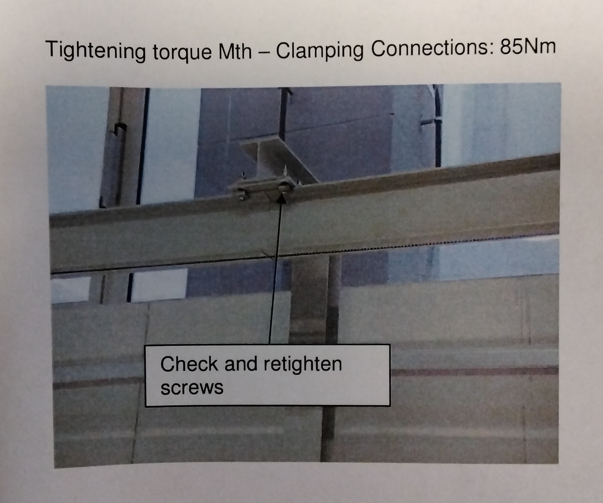
Visually inspect all screw connections annually. It is recommended to retighten screw connections i.e. when impacts occur.
ELECTRICAL DRIVES
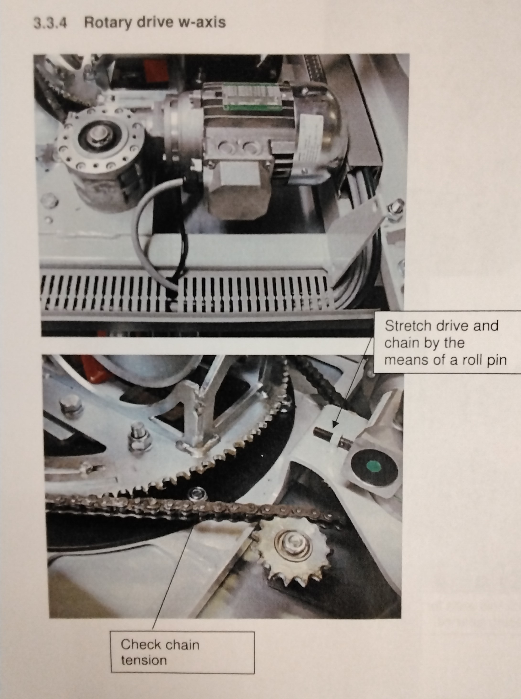
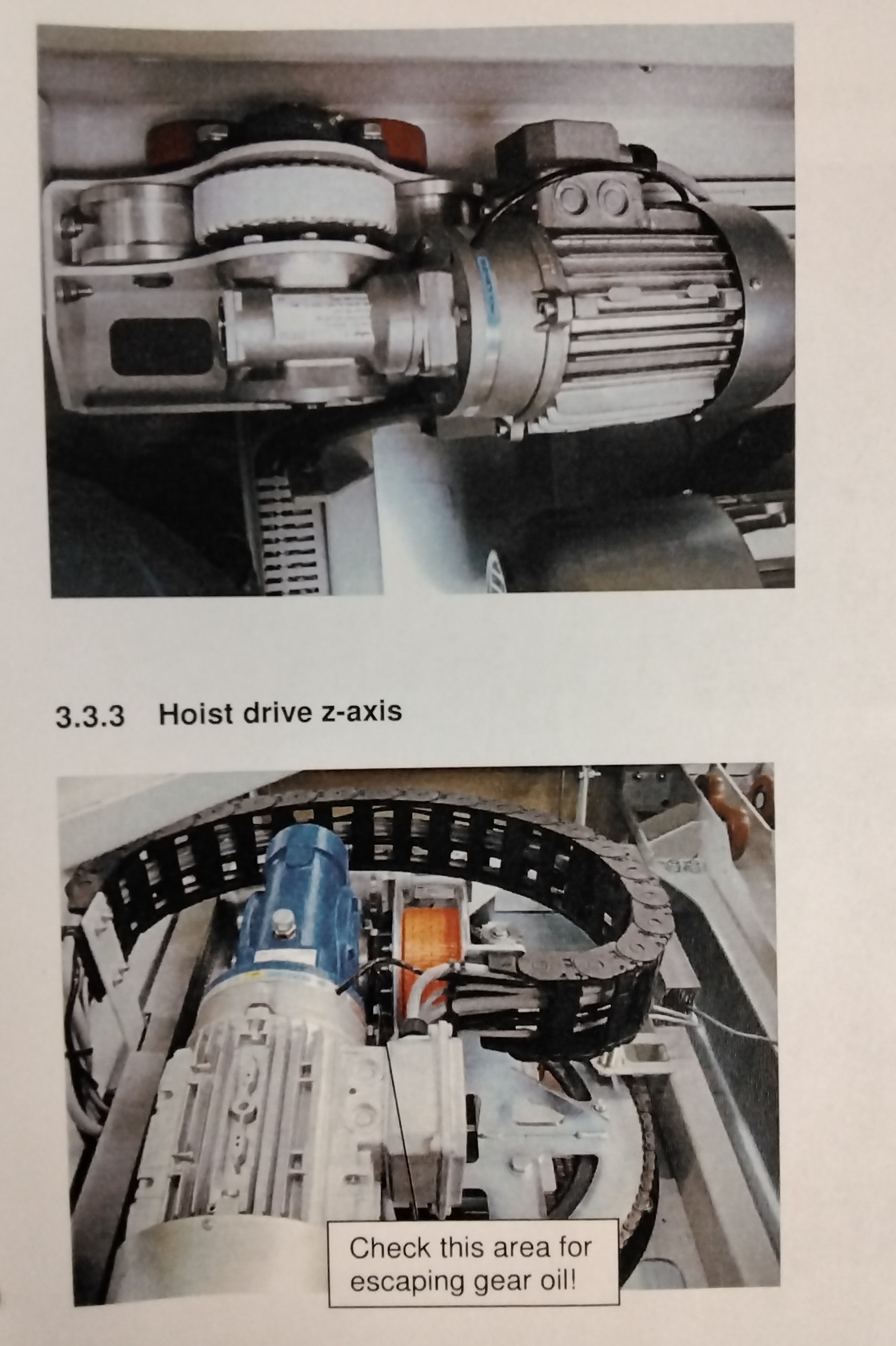
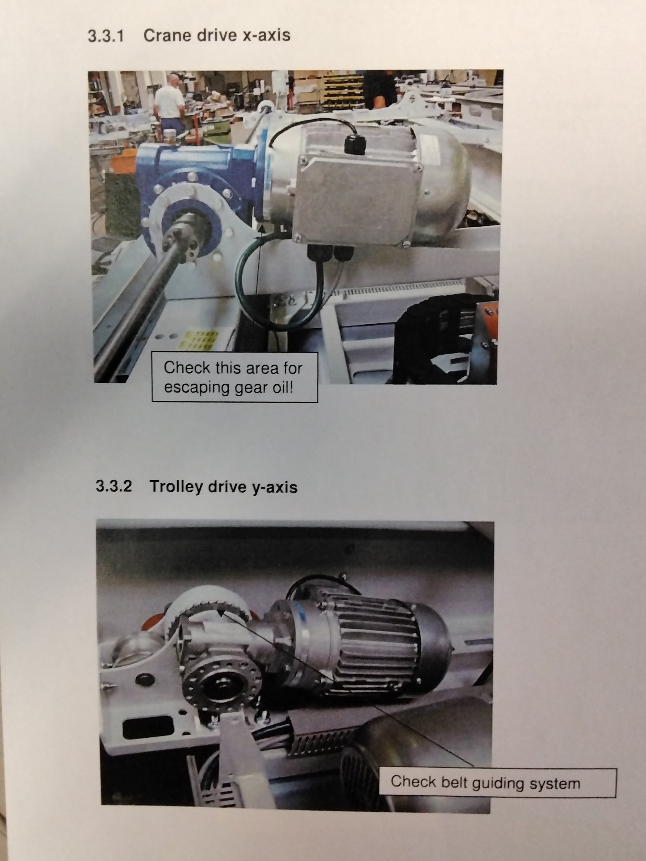
Visual inspection of all electrical drives. Check for chafed cables (encoder cables and motor cables) and or escaping gear oil.
TUBING AND WIRING
Visually inspection of all pneumatic tubing. Immediately exchange kinked or ripped tubes. Visually inspect the wiring of the whole system. Immediately exchange any ripped cables.
MAINTENANCE UNIT
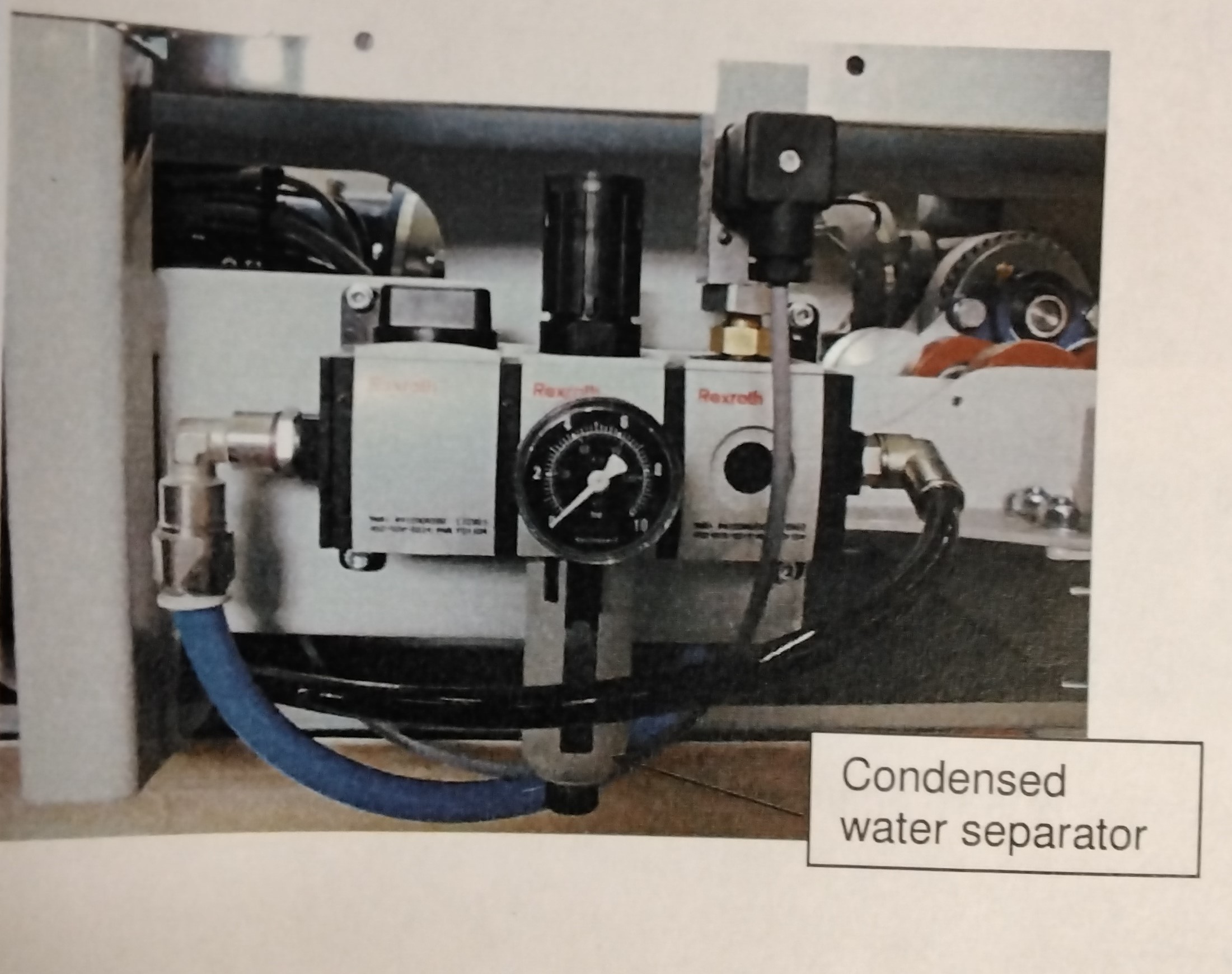
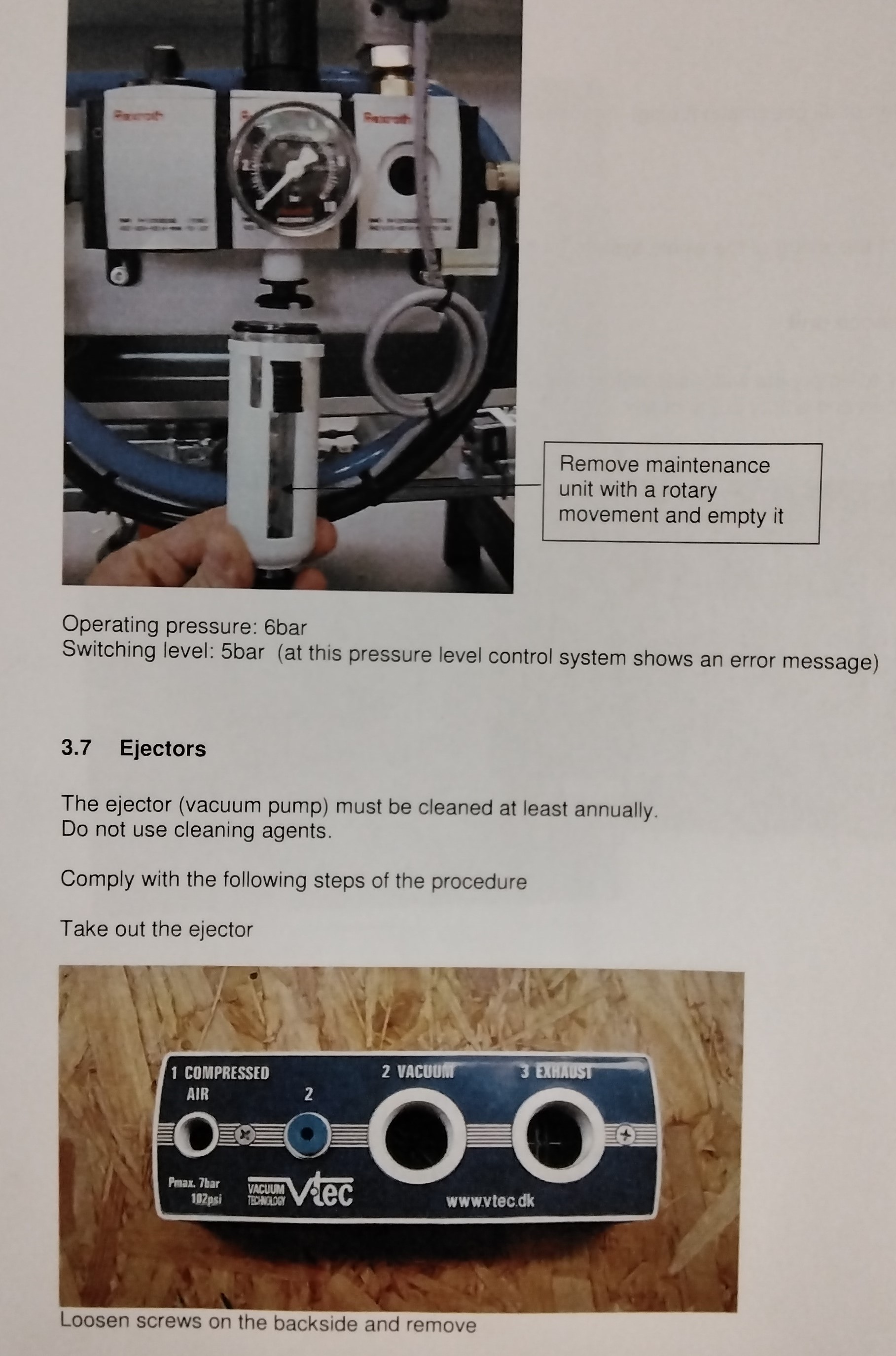
It is necessary to empty the water separator when it has reached a maximum fill level. Otherwise, clean and empty out annually.
EJECTORS
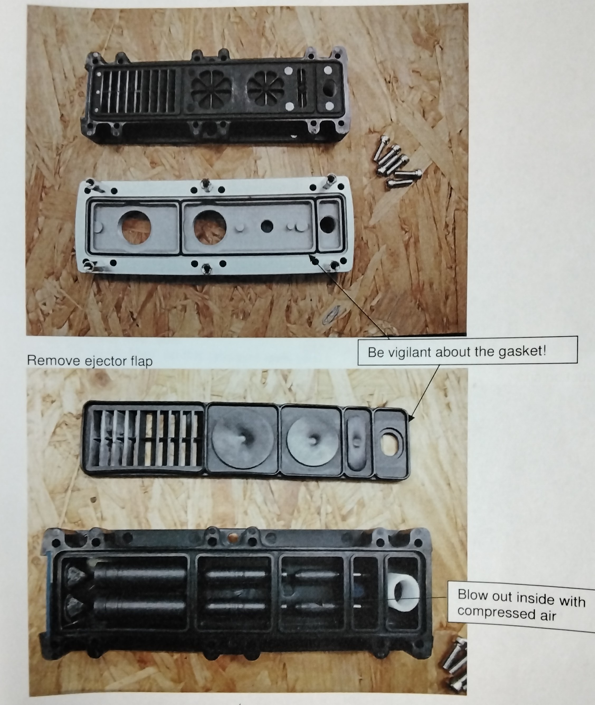
The ejector (vacuum pump) must be cleaned at least annually. Do not use cleaning agents. Comply with the following steps of the procedure: - Take out the ejector: -Loosen screws on the backside and remove - Remove ejector flap (be vigilant about the gasket)! -Blow out inside of the ejector with compressed air and clean it. When reassembling the pieces, it is necessary to be vigilant about the correct position of the gasket.
SUCTION CUPS
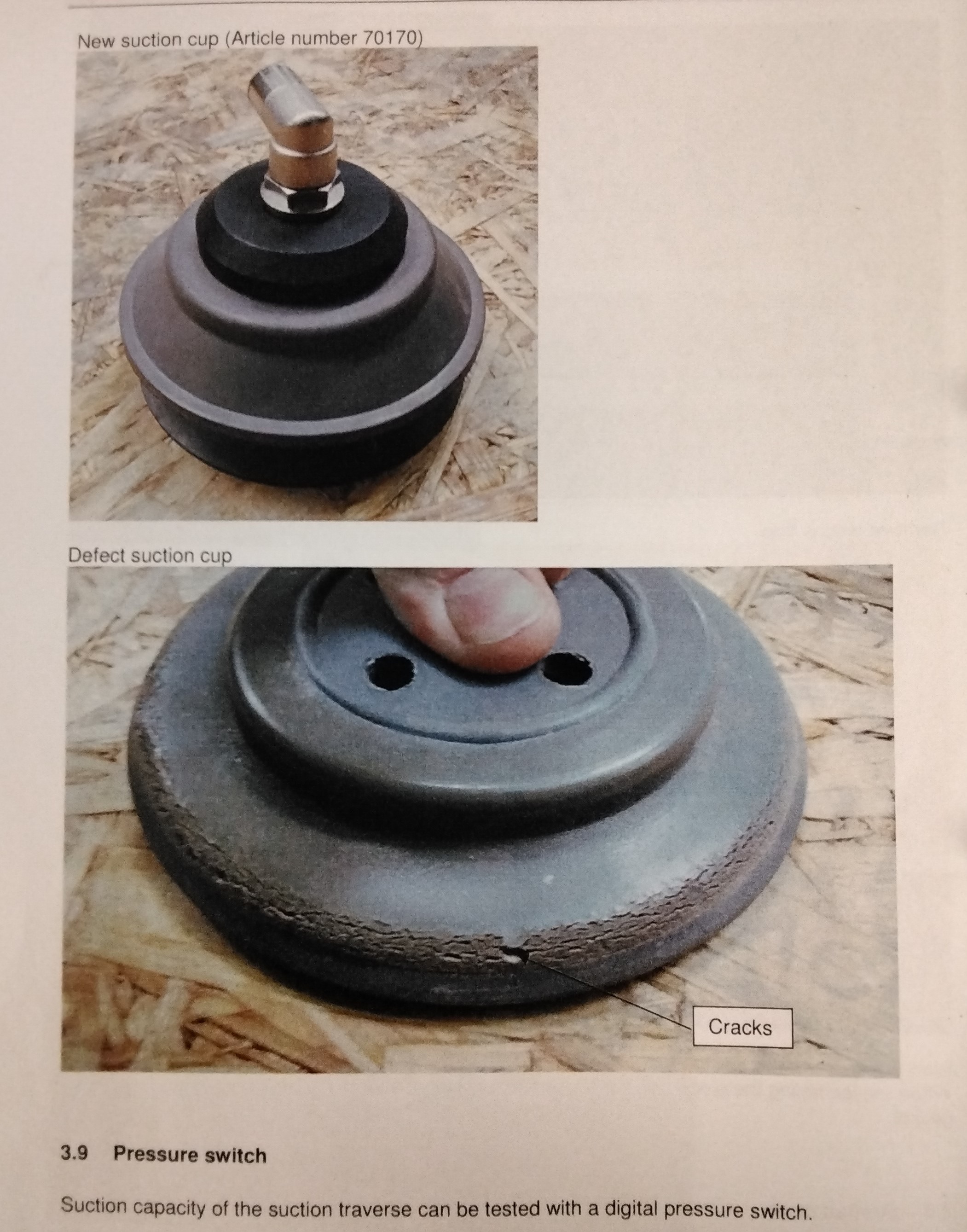
-Cracked and brittle suction cups must be exchanged. Recommended interval of exchange: 150000 lifts or after 1.5 years.
PRESSURE SWITCH
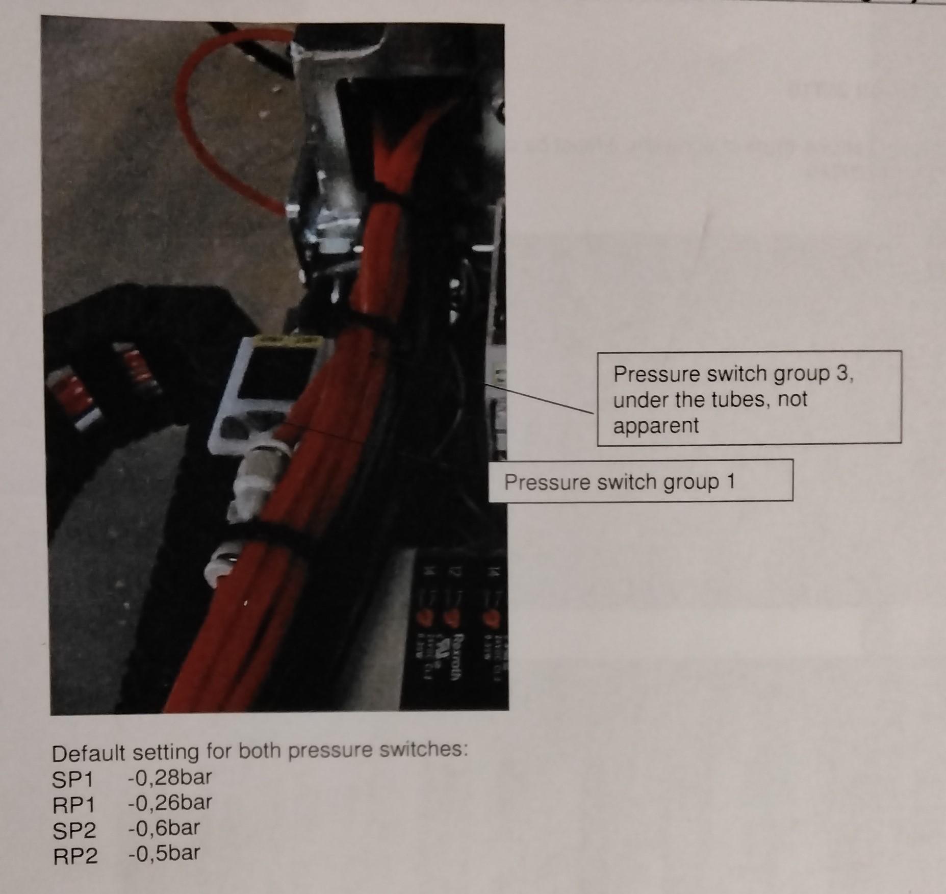
- Suction capacity of the suction traverse can be tested with a digital pressure switch . Default setting for both pressure switches: SP1 -0,28bar RP1 -0,26bar SP2 -0,6bar RP2 -0.5bar On a coated place the vacuum shall reach -0.75bar If this level is not reached, this indicates defect suction cups, a dirty ejector or defect tubing.
DRIVE BELT 25T10
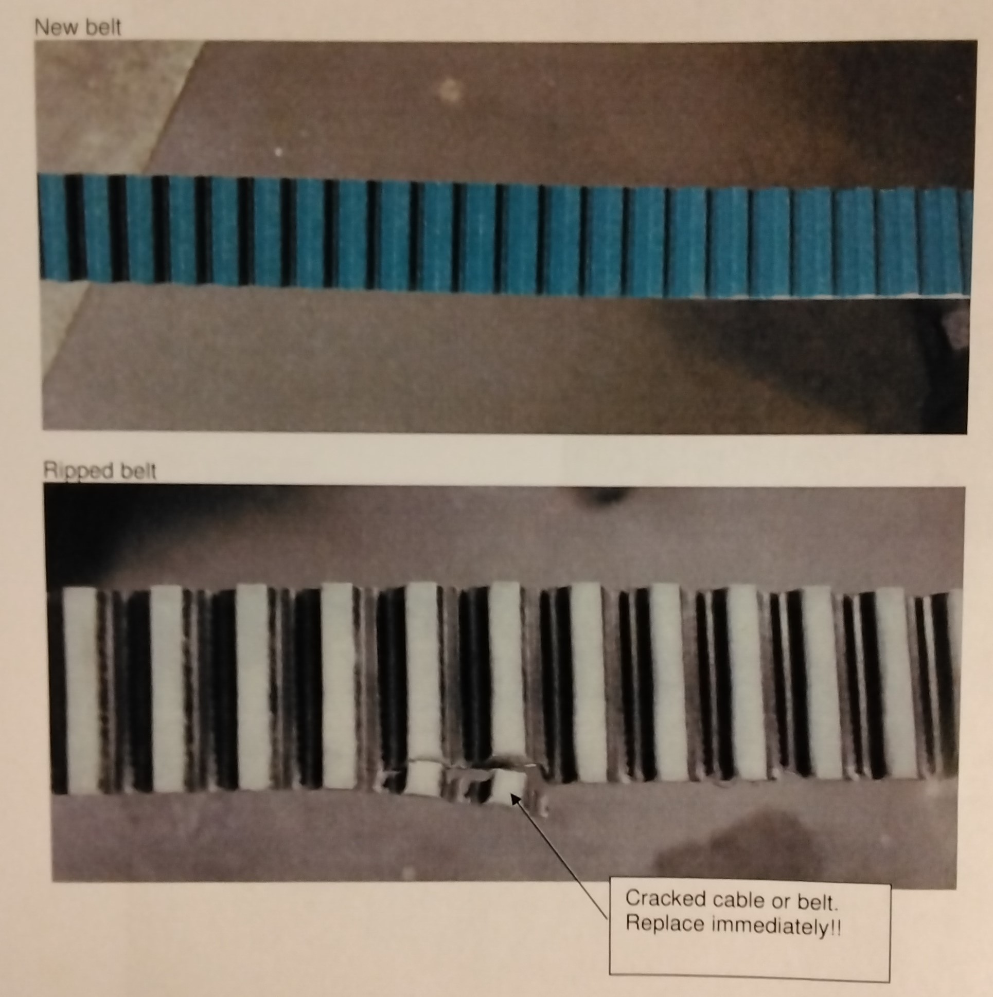
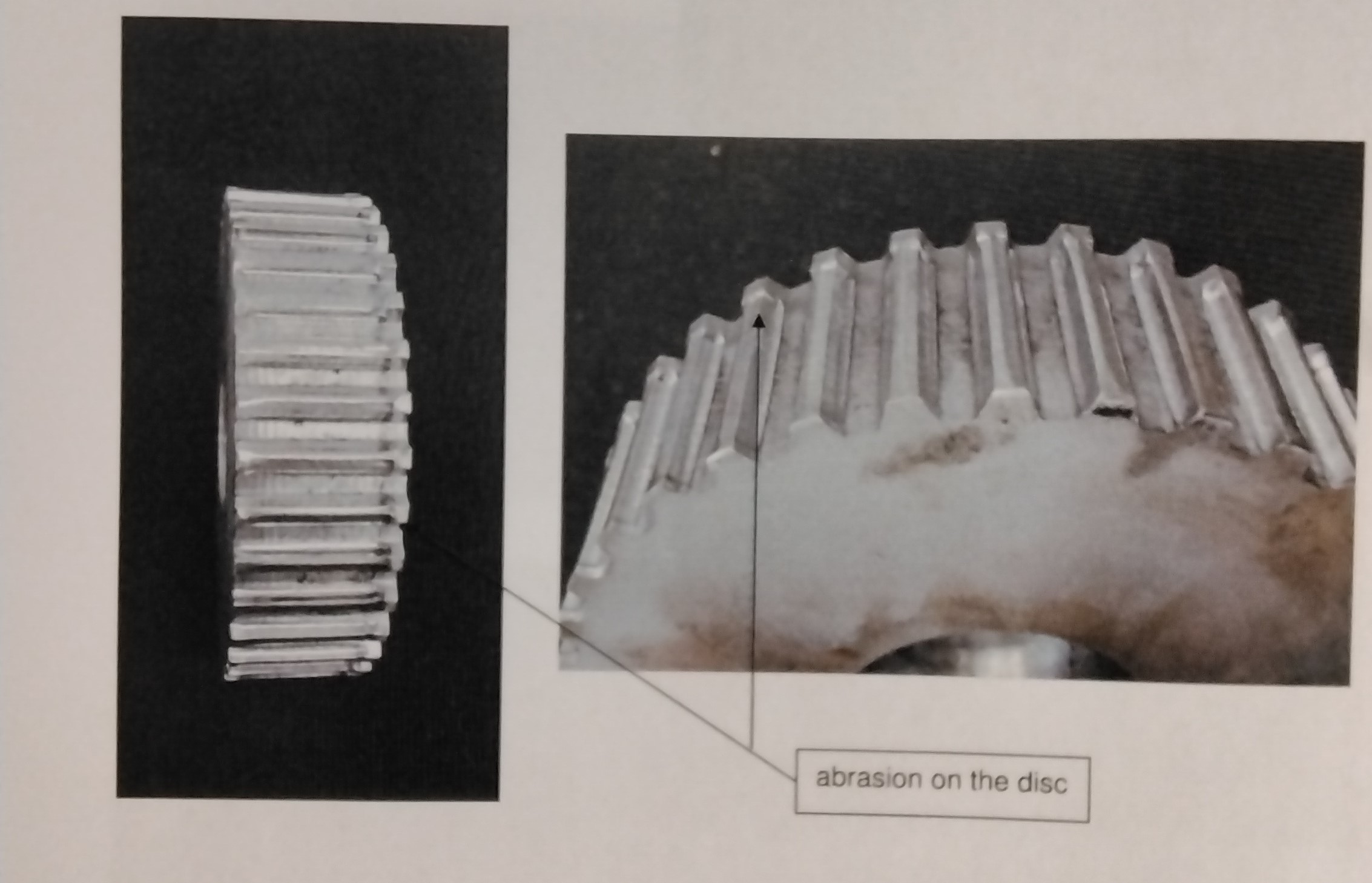
If the drive belt show signs of abrasion, it must be changed immediately. NOTE: The exchange of the drive belt is prescribed after 4000 operating hours or after the maximum of 2 years operating time. Also change the drive belt disc.
DRIVE BELT DISC 30T1036Z
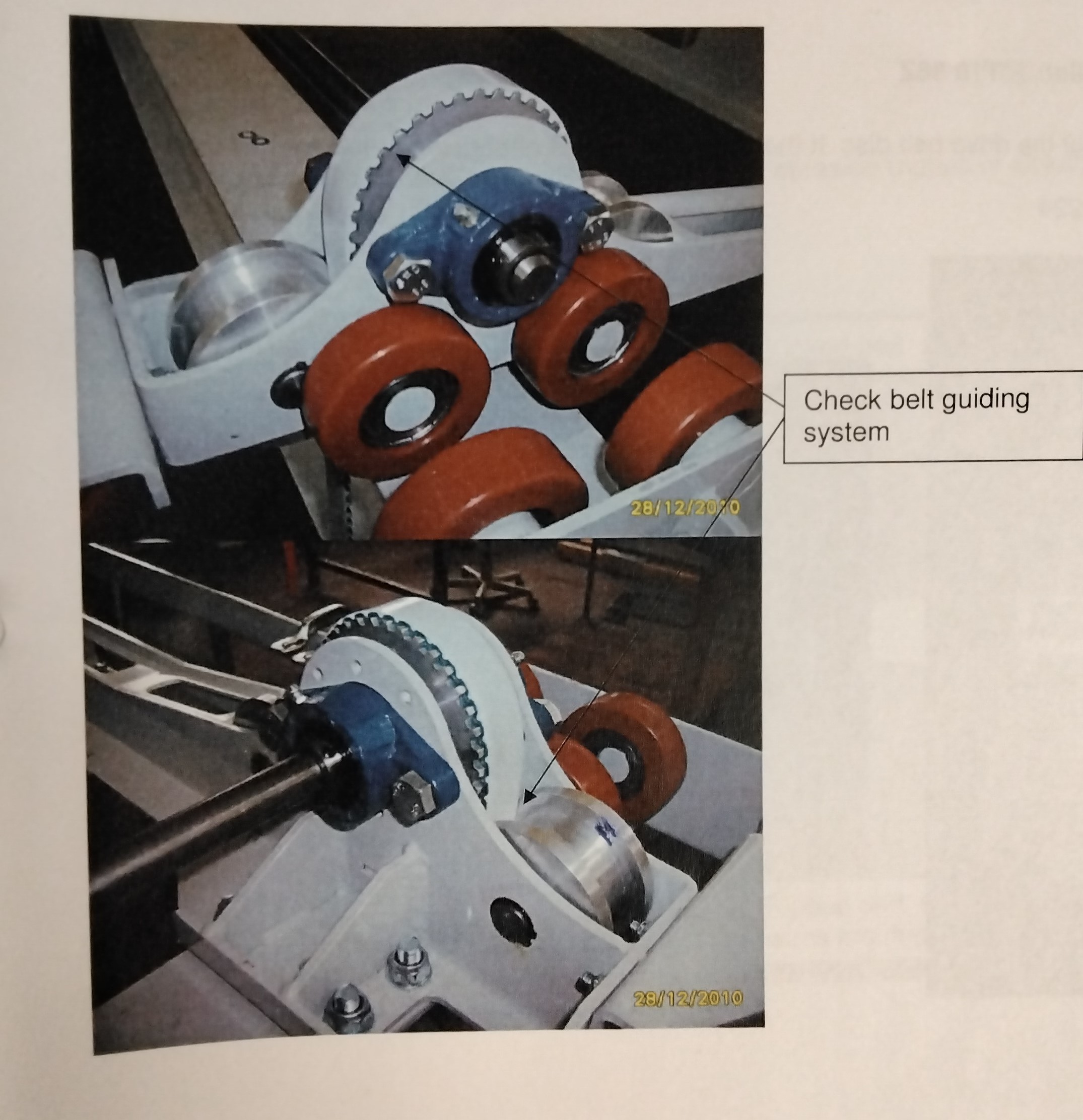
Visual inspection of the drive belt disc. If the disc shows signs of abrasion (picture), immediately exchange it.
CABLE ENCODER
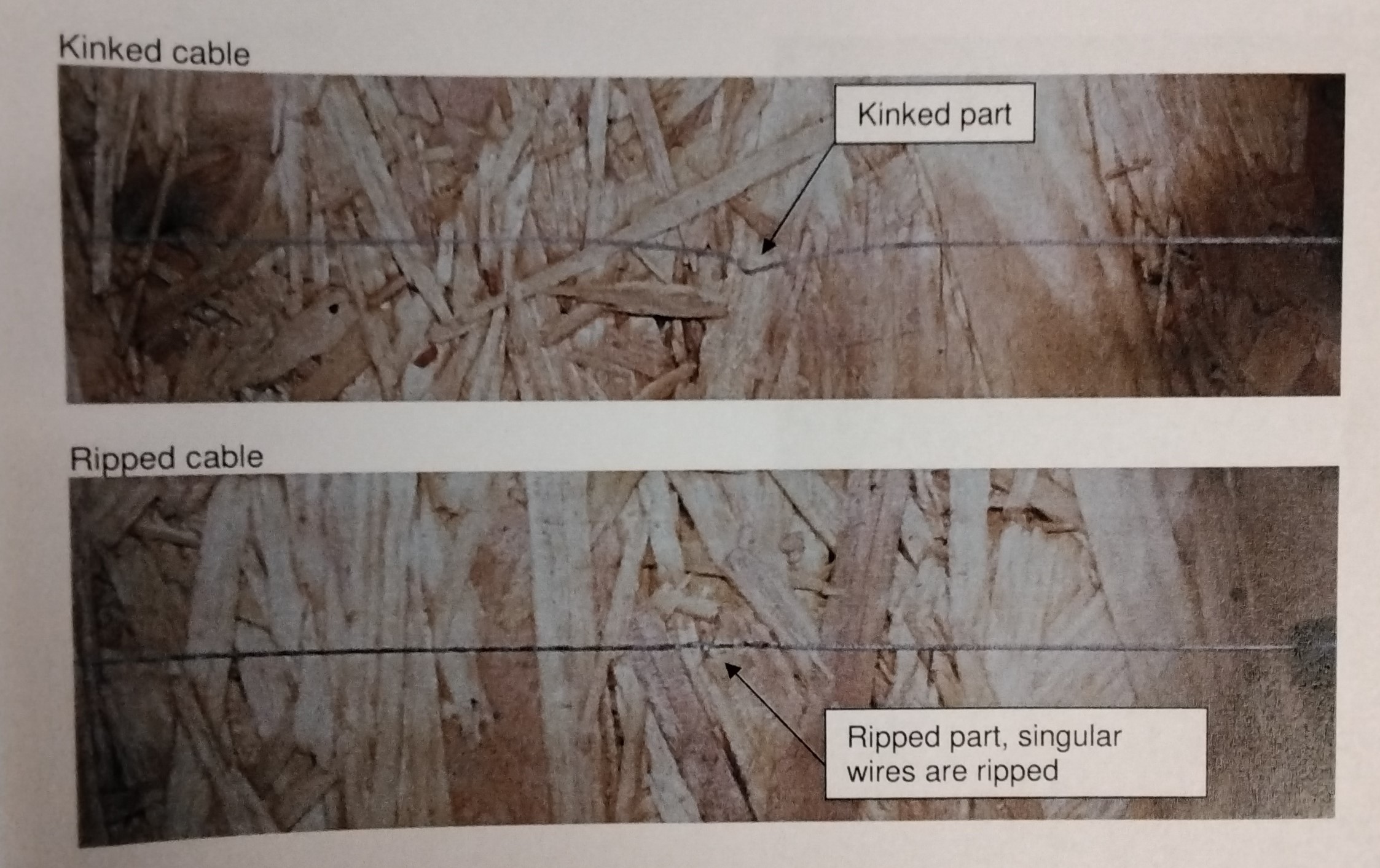
Visual inspection of the cable. If the cable show signs of abrasion (ripped or kinked cable), immediately exchange it.
LIFTING BELT
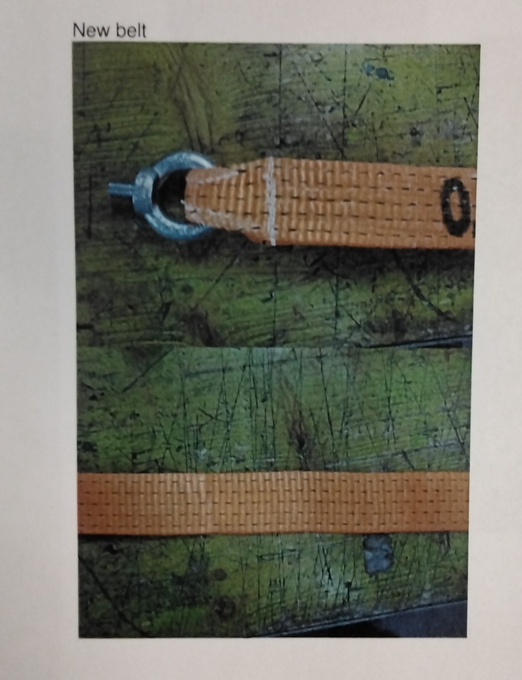
If the lifting belt shows signs of abrasion i.e. rips, it is necessary to exchange it.
ENERGY CHAIN AND WHEEL CONVEYOR
Energy chain: - Check cable carrier system for a proper functioning of the energy chain, Be vigilant about rips or abraded cable in the wiring. Wheel conveyor: -Wheels of the conveyor must be checked for signs of abrasion. Distance between wheel and beam web: 2-3 mm.
SENSORS AND SAFETY SYSTEM
Sensors: -Check all sensors (inductive proximity switch, light sensors, etc.) for their correct functioning and clean them. Furthermore, check sensors for their correct positions (initiator of the switching distance 3-5 mm) Safety System: - Check if safety light barrier at storage place is functioning correctly. Check for a proper anchorage of the safety fence. test EMERGENCY-STOP function regularly. Deficiencies in the safety system must be repaired IMMEDIATELY. Barbaric GmbH shall not be liable for any modification of the safety system.
LUBRICATION
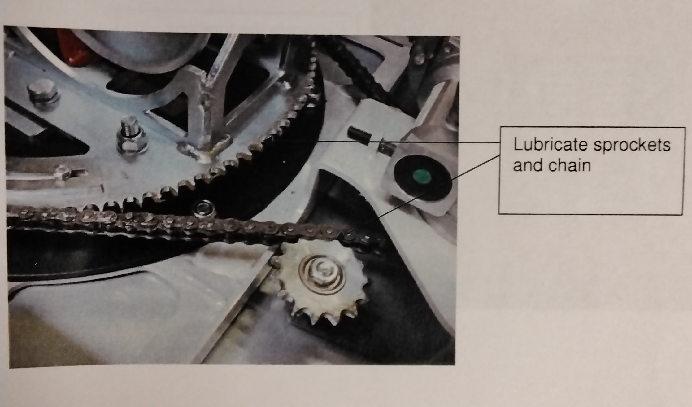
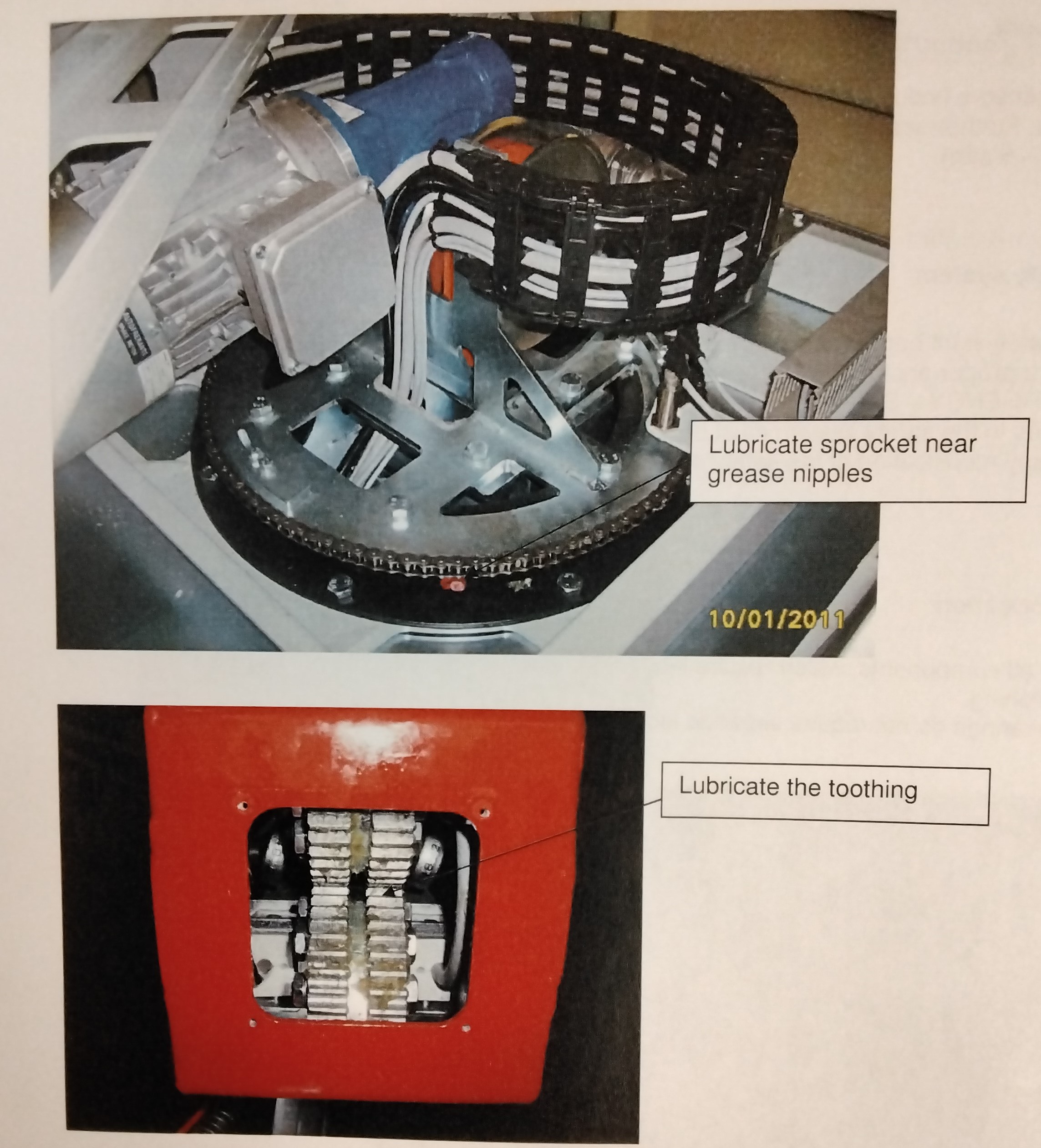
Basically all components, which require lubrication, must be lubricated before the initial commissioning. Flange bearings do not require separate lubrication. -Lubricate sprockets and chain -Lubricate sprocket near grease nipples -Lubricate the toothing.
Source: Ideal Cabinetry (Community Member)


