Stefani Edge Bander Monthly PM
Use this complete guide for the monthly preventive maintenance of your equipment. Regular PMs help you save money by ensuring that your equipment is safe and gives quality performance as it should for a long period of time avoiding down time and money for repair.
Stefani Edge Bander Monthly PM
Use this complete guide for the monthly preventive maintenance of your equipment. Regular PMs help you save money by ensuring that your equipment is safe and gives quality performance as it should for a long period of time avoiding down time and money for repair.
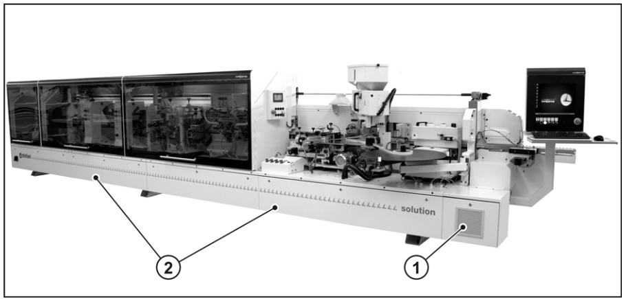
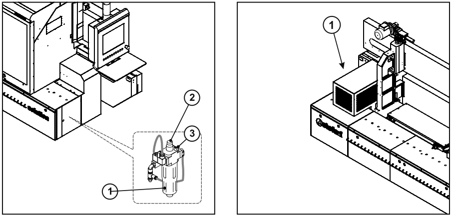
Remove the electric panel cooling system filters (FIG.3-REF.1) and clean using a vacuum cleaner with a specially shaped nozzle. If necessary, replace the filters. clean the inside of the electric panel (FIG.3-REF.2) using a vacuum cleaner with a specially shaped nozzle.
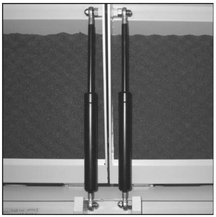
Visual inspect the gas springs (SEE FIG.4) supporting the doors of the sound proof cabin .
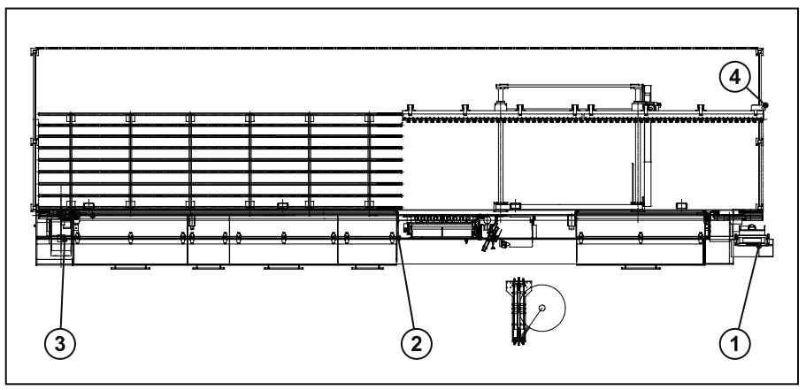
Perform the operating test of the emergency stop push buttons (FIG.5-REF.1, 2,3 and 4). Proceed as follows: (operations to be carried out for all emergency stop push buttons of the machine) • Press the emergency stop push button. • Verify that: a) the push button remains pressed; b) the pneumatic unit depressurizes quickly. c) the spindles stop within 10 seconds
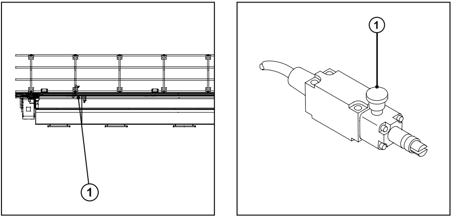
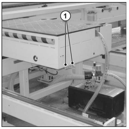
Perform the operating test of the cord activated emergency stop devices (FIG.6-REF.1). Proceed as follows: (operations to be carried out for all cords emergency stop devices of the machine) • Move the cord. • Verify that: a) the ratchet lowers (FIG.7-REF.1); b) the pneumatic unit depressurizes quickly; c) the spindles stop within 10 seconds;
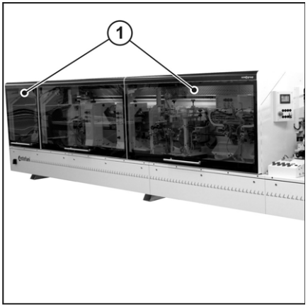
Perform the operational test of the sound proof cabin doors interlocking devices (FIG.8-REF.1) (except for the gluing unit door, if present). Proceed as follows: (operation to be performed on each sound proof cabin door) • Verify that the locking device does not allow the door to be opened. • Stop the machine and verify that the door does not open earlier than 10 seconds from the stopping command.
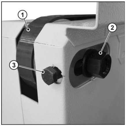
If necessary tension the belt (FIG.13-REF.1), proceed as follows: • Loosen the nut (FIG.13-REF.2). • Adjust the screw (FIG.13-REF.3), ensuring that the belt is not tensioned excessively. • Tighten the nut (FIG.13-REF.2)
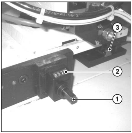
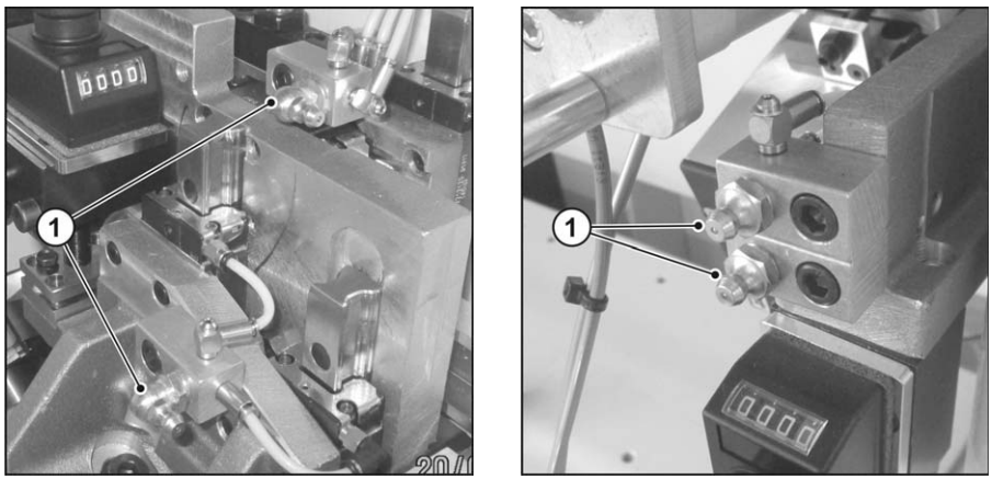
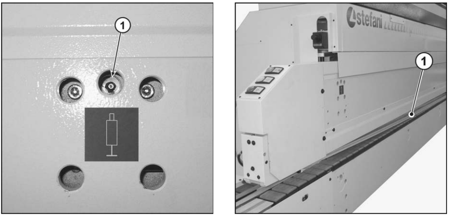
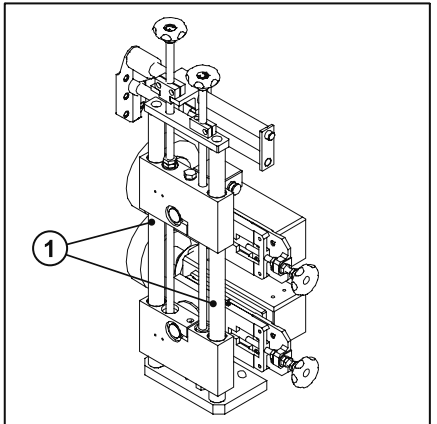
Remove any dust and shavings from the guides with recirculating ball bearing pads (FIG.15-REF.3) with a vacuum cleaner with a suitably shaped nozzle and a soft dry cloth. Move the upper boards along a complete stroke (towards the feed track and back after greasing. Guides with pads and ball bearings lubricate the ballscrews. • Use the appropriate greasers (FIG.21-REF.1). Use AGIP GR MU EP 1 grease (or equivalent).
• CHAIN CLEANING Every 40 work hours and whenever else it is necessary, clean the pads with compressed air and/or using a vacuum cleaner with a suitably shaped nozzle. • CHAIN LUBRICATION Every 40 work hours check the oil level in the lubricating device cup (FIG.16-REF.1). If necessary top up. Proceed as follows: • Unscrew the cup (FIG.16-REF.1). • Top up with INTERFLON – IF FOOD LUBE G150 oil. • Tighten the cup (FIG.16-REF.1
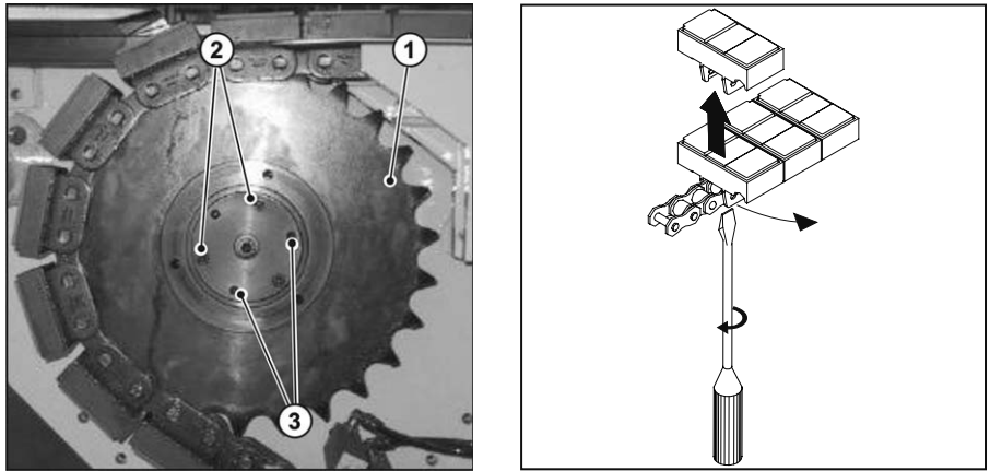
ADJUSTING THE DRIVEN SPROCKET If the panels are not parallel as they advance, the driven sprocket must be shifted on its axle (FIG.19- REF.1). Proceed as follows: • Remove the infeed protection of the feed track (FIG.18-REF.1). • Adjust the screws (FIG.19-REF.2) and the grub screws (FIG.19-REF.3). Remember that the screws “pull” and the grub screws “push”. • Install the infeed protection of the feed track (FIG.18-REF.1 REPLACEMENT OF THE PAD Proceed as follows: • Position the pad to be changed by the driven sprocket. • Remove the infeed protection of the feed track (FIG.18-REF.1). • Insert a flat screwdriver between the chain and the pad and remove the pad (s. FIG.20). • Replace the pad. • Install the infeed protection of the feed track (FIG.18-REF.1)
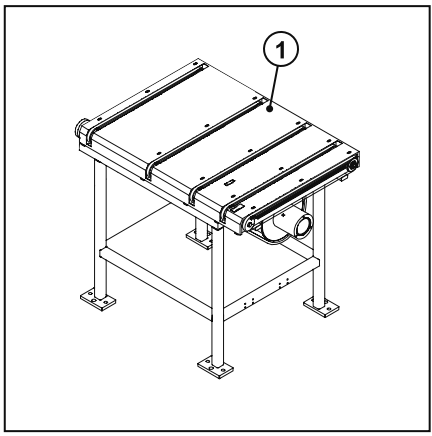
LUBRICATING THE LIFTING DEVICE MACHINE STATUS: off, with the main switch in the “0” position. “0” position and padlocked, and the compressed air stop cock closed and padlocked. OPERATORS: 1 maintenance mechanic. Every 160 working hours lubricate the lifting device of the presser by using grease AGIP GR MU EP 1 (or equivalent). Use the lubricating devices (FIG.21-REF.1). BELT INSPECTION MACHINE STATUS: off, with the main switch in the “0” position. “0” position and padlocked, and the compressed air stop cock closed and padlocked. OPERATORS: 1 maintenance mechanic. Every 1000 hours (6 months) visually inspect the internal and external surfaces of the belt (FIG.22- REF.1). If any tears and/or material missing is found contact the manufacturer (s. par. 2.1).
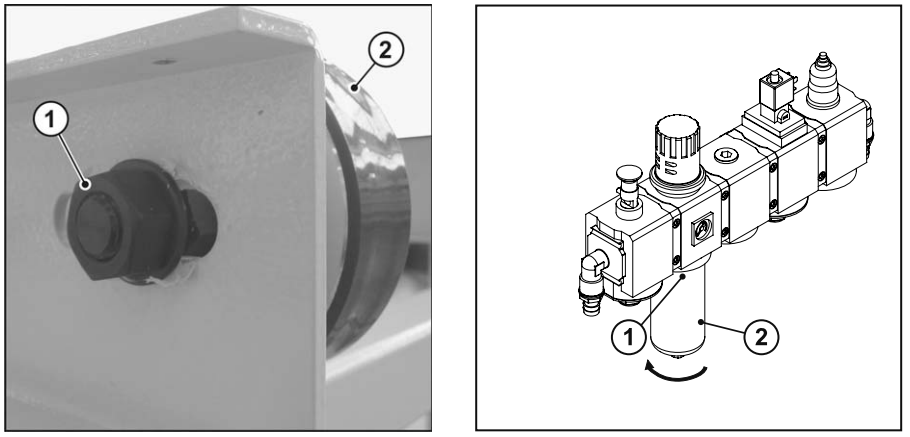
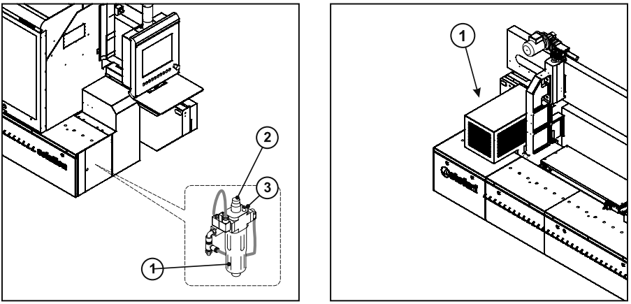
BELT TENSION If required, tighten the belts as follows: • Remove the guard (FIG.29-REF.1). • Loosen the nut (FIG.30-REF.1). • Tension the belt (FIG.30-REF.2). • Block the nut (FIG.30-REF.2). • Fit the guard (FIG.29-REF.1) Replace the filter cartridge. Proceed as follows: • Keep the release clip pressed (FIG.31-REF.1). • Rotate the tank counterclockwise (FIG.31-REF.2). • Replace the filter cartridge.
Check the oil level in the lubricating device cup (FIG.16-REF.1). If necessary top up. Proceed as follows: • Unscrew the cup (FIG.16-REF.1). • Top up with INTERFLON – IF FOOD LUBE G150 oil. • Tighten the cup (FIG.16-REF.1) The gear motor (FIG.17-REF.1) is supplied with ISO VG 320 synthetic oil. Every 4000 work hours check the oil level. If required, top up. Every 20000 work hours replace oil
Remove dust and shavings from the unit using a vacuum cleaner with a suitably shaped nozzle. Complete the cleaning process using a dry cloth and lubricate them with AGIP GR MU EP 1 (or equivalent). -Grease fitting on the front of each station With AGIP GR MU EP 1
Source: Ideal Cabinetry (Community Member)

