Project Report
Concise and informative document that captures the essential details of a visit. It provides a summary of the purpose and scope of the visit, the individuals or entities visited, and any challenges faced during the visit. The report also outlines any noteworthy achievements or successes and offers recommendations for further action or follow-up. Overall, a visit report serves as a valuable reference tool for future planning and decision-making.
Procedure Max Score: 34
Information
Visit Purpose
Customer Info
Date of Visit
Goals
General Information
Safety
Safety Guards
Safety Notes
Imagenes
Add or drag pictures
Assembly
The dryer will generally be assembled under supervision of Geelen Counterflow. This manual contains general instructions how to assemble and connect electrical devices. The sequence of assembly depends strongly on the local situation. The dryer and cooler should be unloaded from truck or container before the assembly supervisor from Geelen arrives. During the assembly, a forklift truck with a minimal lifting capability of 3 metric tons and long forks should be available. Often parts are lifted in the building via the roof by means of a crane with a maximum load of approximately five metric tons. The dryer will be pre-assembled in modules on the ground, as close as possible to the building in order to avoid transport damage.
Compress Air
Compress Air
Compressed air has to be dry with a minimal pressure of 6 bar and a maximum pressure of 8 bar. The use of lubricated air is advised. For compressed air supply every solenoid valve must be provided with a valve to make the system pressure less. Synthetic air ducts or connections must not be mounted against bin, hood and air ducting. In case of a fire these synthetic ducts can melt.
Gas Connection
Rake with torque limiter
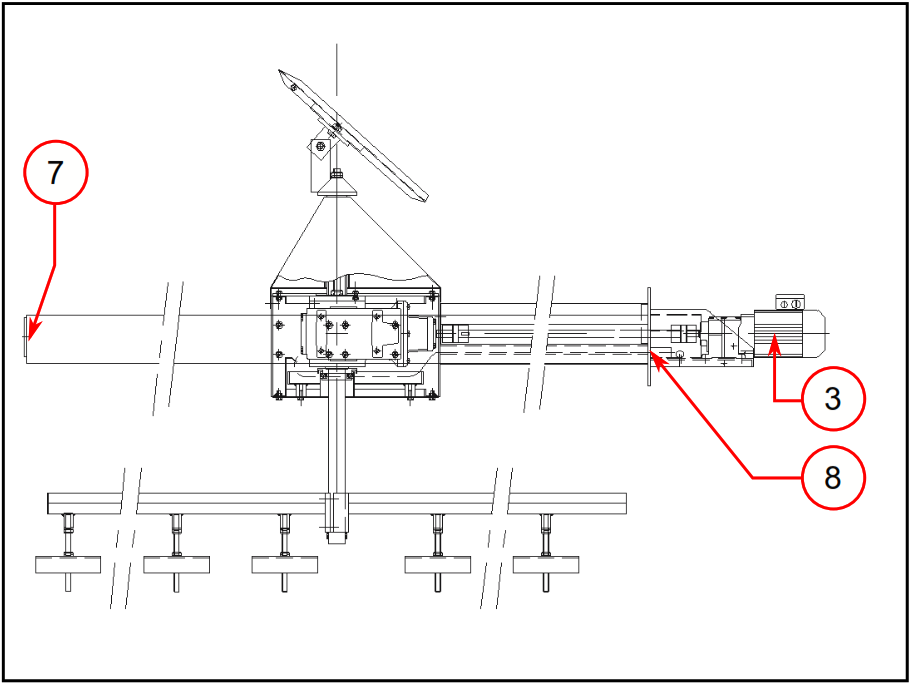
Rake with fixed height (option) The drive of the rotating product distributor/rake is supplied completely pre-assembled.
Assembly the fram
The drive of the rotating product distributor/rake is supplied completely pre-assembled.
Check by turning the drive shaft manually
Torque limiter
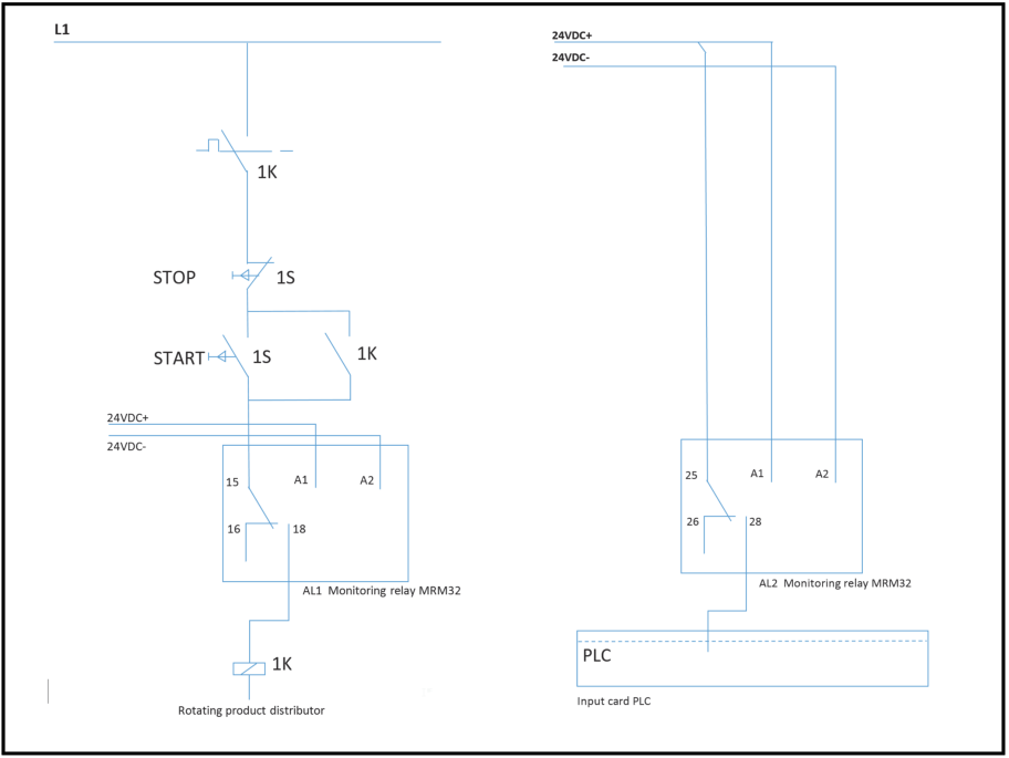
The torque limiter must be installed according to the diagram below; in case a PLC is used, the second output is used for an input of the PLC generating an alarm
Hydraulic Unit
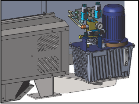
For transportation reasons the hydraulic unit is supplied separately.
Dryers
The support of the dryer’s discharger is fitted with a stationary support for the hydraulic unit. Place the hydraulic unit on the support and secure it with bolts.
Connections can be made
Rotating Sensor
Fixed Position
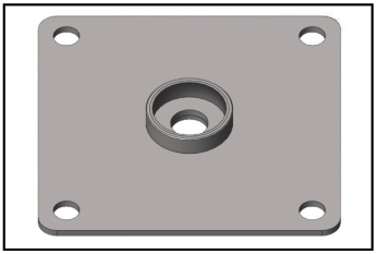
In the fixed position the sensor is screwed in a base plate and detects the product level at that particular location.
Movable Position
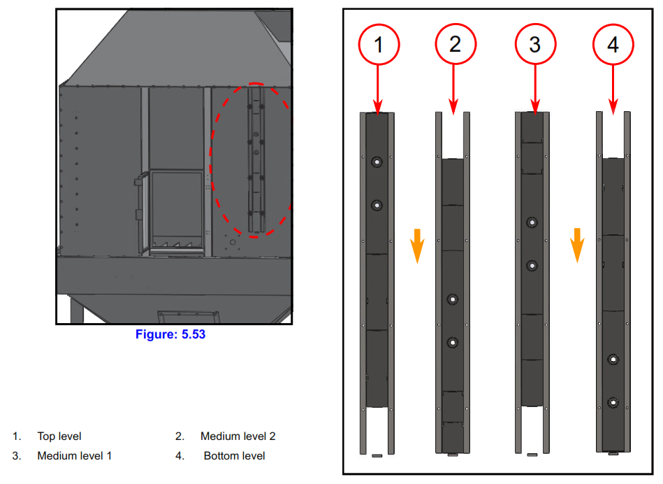
In case of a movable position, different cover plates are used in order to set the height for the level sensor. The plates can be mounted in 4 different ways, every height can be reached:
Temperature Probe
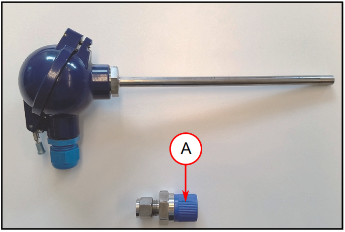
For measuring air temperatures in order to control and monitor the process during product cooling/drying, temperature probes can be installed in the machine and air system.
PT100 Installation
Preventative Maintenance
If your equipment is well maintained, it's less likely to breakdown, which leads to increased uptime, more working hours for the equipment, fewer repair costs, and therefore increased revenue.
Rotary Valve
Check blades and housing for signs of wear
Check coupling for friction
Check oil level of the gearbox
Replace oil of the gearbox
Signatures
Rake with Torque Limiter
Check cooling air
Check coupling
Replace oil of the gearbox
Check whether paddles of rake and the distributor are adjusted correctly (45°); check leakage gearbox
Swivel valve discharger
Check Hydraulic cylinders at each deck.
Check Oil level and Hydraulic hoses, pipes, connections, etc.
Check oil colour and filter state
Check ball-joints at the cylinders and swivel arms on each deck.
Drain all oil, clean the unit, fill with new oil.
Replace oil filter
Bearings
Commissioning
All Geelen Counterflow dryers are sold with control systems and commissioning by a Geelen Counterflow engineer. The Geelen Counterflow engineer will start commissioning on site. If for some reason there is no commissioning by a Geelen Counterflow engineer, use the steps mentioned below as a reference.
Commissioning before trial operation (no power to unit)
The wiring diagrams are accompanied by a terminal strip which indicates which components must be connected to which terminals. Use this terminal strip to check whether all the terminals in the box are actually and correctly connected.
• Warn all those present before switching on the power • Switch on all motors in manual mode and check the direction of rotation of the motors. • Check whether the gate opens and closes as described in the relevant section.
Starting up for the first time (Continuous dryer)
Before starting up the system, several basic parameters should be set on the machine.
Adjust the product level sensors to a product layer thickness of 30 – 50 cm. Overflow sensors on each deck prevent overfilling of the decks.
Product distributor
In case of a continuous dryer, set the quantity of product to be discharged per unit of time. Set the open and close positions to approximately 25% and 15%. Each discharge should lower the product bed depth with 2-3 cm. It is recommended to use a base setting of 10 seconds between strokes, when starting the machine for the first time.
Determine the minimum and maximum values to be set as defined for this dryer. Make sure that the product’s fluidization air speed is not reached.
Set the temperature of the drying air entering the dryer to the value as determined for this project.
Starting up for the first time (Batch Dryer)
Before starting up the system, several basic parameters should be set on the machine.
In case of a batch dryer no level sensors are used for maintaining the product layer thickness, as discharging is controlled by a batch timer. Overflow sensors on each deck prevent overfilling of the decks.
Adjust the belt distributor, please refer to the corresponding chapter of the manual for instructions.
In case of a batch dryer, set the residence time of the product on the deck (batch time). Each discharge cycle should completely discharge the product from one deck to the next (or hopper).
Determine the minimum and maximum values to be set as defined for this dryer. Make sure that the product’s fluidization air speed is not reached.
Set the temperature of the drying air entering the dryer to the value as determined for this project.
Verify correct operation of buttons
Starting (during commissioning)
Batch dryer basic
Continous dryer specific
Press “Stop”. The system should stop
Manual discharge of gate
Emptying system
In case of a batch deck, a deck is emptied automatically.
Continuous dryer specific
Spare Parts
Dryer Gas Burner (Spare Parts)
Spare Parts Minimum
Spare Parts Recommended
Dryer Steam Heater (Spare Parts)
Spare Parts Minimum
Spare Parts Recommended
Field Service Signature
Click here to sign
Source: Geelen Counterflow (Community Member)


